МЕХАНИЧЕСКАЯ ТРАНСМИССИЯ В СБОРЕ (для моделей с 1WW) СНЯТИЕ
-
PRECAUTION
Note
After turning the ignition switch off, waiting time may be required before disconnecting the cable from the battery terminal. Therefore, make sure to read the disconnecting the cable from the battery terminal notice before proceeding with work Click here.
-
DISCONNECT NEGATIVE BATTERY TERMINAL
Note
When disconnecting the cable, some systems need to be initialized after the cable is reconnected Click here.
-
REMOVE NO. 1 ENGINE UNDER COVER
-
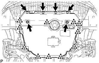
Выверните 6 болтов и снимите 11 фиксаторов.
-
Снимите нижнюю крышку двигателя № 1.
-
-
REMOVE STARTER ASSEMBLY
-
REMOVE EXHAUST PIPE ASSEMBLY
-
REMOVE FRONT LOWER BUMPER ABSORBER
-
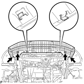
Отверните 4 болта.
-
Отцепите 2 зацепа переднего нижнего поглотителя энергии удара от установочных отверстий в кузове и снимите передний нижний поглотитель энергии удара.
-
-
REMOVE ENGINE UNDER COVER REAR RH
-
Снимите 5 фиксаторов и снимите правую заднюю защиту картера двигателя.
-
-
REMOVE ENGINE UNDER COVER REAR LH
-
Снимите 5 фиксаторов и снимите левую заднюю защиту картера двигателя.
-
-
DRAIN MANUAL TRANSAXLE OIL
-
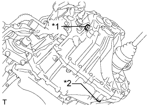
Text in Illustration *1 Filler Plug *2 Drain Plug Remove the filler plug and gasket.
-
Remove the drain plug and gasket to drain the manual transaxle oil.
-
Install a new gasket and the drain plug.
- Torque:
- 39 N*m { 400 kgf*cm, 29 ft.*lbf }
-
-
REMOVE DRIVE SHAFT ASSEMBLY
-
DRAIN ENGINE COOLANT
CAUTION:
Не снимайте пробку расширительного бачка радиатора и клапан для выпуска воздуха, пока двигатель и радиатор не остынут. Выброс горячей охлаждающей жидкости и пара под давлением может стать причиной серьезных ожогов.
-
Ослабьте пробку сливного крана радиатора и слейте охлаждающую жидкость двигателя.
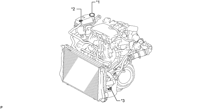
Обозначения на рисунке *1 Пробка расширительного бачка *2 Клапан для выпуска воздуха *3 Пробка сливного крана радиатора - - Tech Tips
Слейте охлаждающую жидкость в резервуар и утилизируйте ее в соответствии с местными требованиями.
-
Снимите пробку расширительного бачка.
-
-
REMOVE NO. 1 ENGINE COVER
-
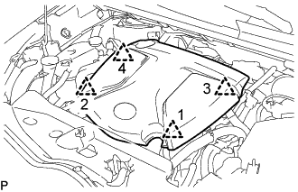
Поднимите крышку двигателя № 1, чтобы освободить 4 фиксатора в порядке, показанном на рисунке, и снимите крышку двигателя № 1.
Note
Попытка одновременно освободить задние и передние фиксаторы может привести к повреждению крышки двигателя № 1.
-
-
REMOVE AIR CLEANER CAP SUB-ASSEMBLY WITH AIR CLEANER HOSE ASSEMBLY
-
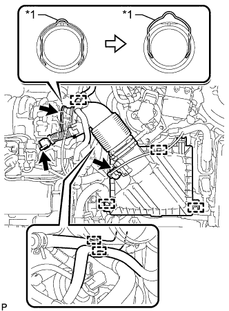
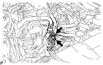
Text in Illustration *1 Retainer Detach the clamp and disconnect the mass air flow meter sub-assembly connector.
-
Detach the clamp and disconnect the vacuum hose from the air cleaner hose assembly.
-
Detach the clamp and disconnect the No. 1 fuel hose from the air cleaner hose assembly.
-
Detach the clamp and disconnect the No. 2 fuel hose from the air cleaner hose assembly.
-
Disconnect the ventilation hose from the cylinder head cover sub-assembly.
-
Release the retainer and disconnect the air cleaner hose assembly from the turbocharger sub-assembly as shown in the illustration.
-
Detach the 2 clamps and remove the air cleaner cap sub-assembly with air cleaner hose assembly.
-
-
REMOVE AIR CLEANER FILTER ELEMENT SUB-ASSEMBLY
-
REMOVE AIR CLEANER CASE SUB-ASSEMBLY
-
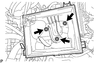
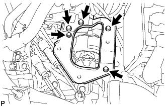
Remove the 3 bolts and air cleaner case sub-assembly.
-
-
REMOVE AIR CLEANER BRACKET
-
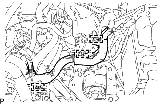
Disconnect the 3 clamps and wire harness.
-
Remove the 5 bolts and air cleaner bracket.
-
-
REMOVE WIRE HARNESS
-
Detach the 2 clamps from the No. 1 air tube assembly.
-
Remove the 2 bolts and disconnect the engine wire from the No. 1 air tube assembly.
-
-
REMOVE NO. 4 WATER BY-PASS HOSE
-
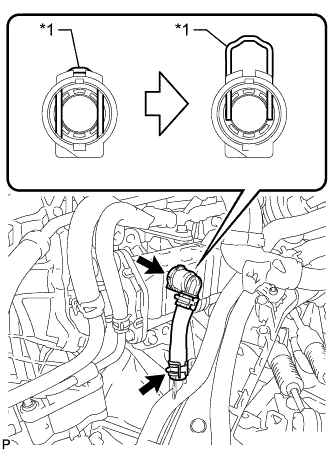
Text in Illustration *1 Retainer Release the retainer and disconnect the No. 4 water by-pass hose from the EGR cooler assembly as shown in the illustration.
-
Slide the clamp and remove the No. 4 water by-pass hose from the No. 2 radiator pipe.
-
-
DISCONNECT COMPRESSOR OUTLET ELBOW
-
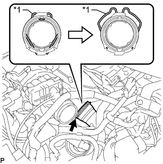
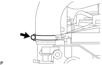
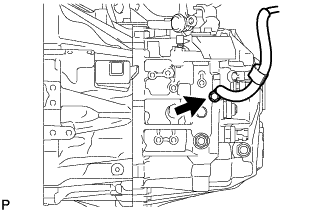
Text in Illustration *1 Retainer Release the retainer and disconnect the compressor outlet elbow from the turbocharger sub-assembly as shown in the illustration.
-
-
DISCONNECT INTERCOOLER AIR HOSE
-
Ослабьте хомут шланга и отсоедините воздушный шланг промежуточного охладителя воздуха от промежуточного охладителя воздуха в сборе.
-
-
REMOVE NO. 1 AIR TUBE ASSEMBLY
-
Slide the clamp and disconnect the water by-pass hose assembly from the No. 2 radiator pipe.
-
Slide the clamp and disconnect the radiator hose sub-assembly from the No. 1 radiator pipe.
-
Detach the clamp and disconnect the water hose sub-assembly from the compressor outlet elbow.
-
Slide the clamp and disconnect the water hose sub-assembly from the No. 1 radiator pipe.
-
Slide the clamp and disconnect the outlet heater water hose from the No. 2 radiator pipe.
-
Remove the 2 bolts and disconnect the No. 1 air tube assembly from the manual transaxle assembly.
-
-
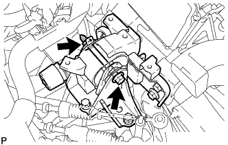
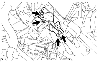
DISCONNECT TRANSMISSION CONTROL CABLE ASSEMBLY
-
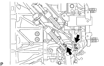
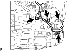
Remove the 2 clips and disconnect the 2 cables from the manual transaxle assembly.
-
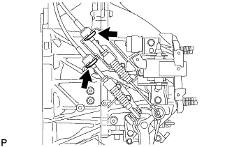
Remove the 2 clips and disconnect the 2 cables from the control cable bracket.
-
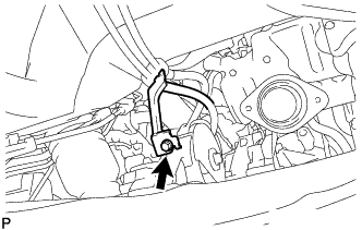
Remove the bolt and detach the bracket of the transmission control cable assembly.
-
-
REMOVE NO. 1 CLUTCH HOUSING COVER
-
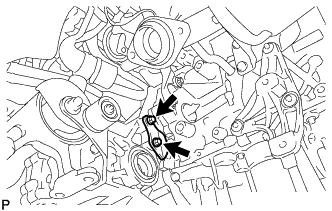
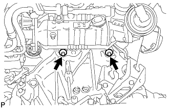
Remove the 2 bolts and No. 1 clutch housing cover.
-
-
REMOVE NO. 2 MANIFOLD STAY
-
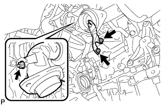
Using an E14 "TORX" socket wrench, remove the 2 bolts from the manual transaxle assembly.
-
Remove the nut and No. 2 manifold stay.
-
-
DISCONNECT CLUTCH RELEASE CYLINDER ASSEMBLY
-
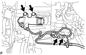
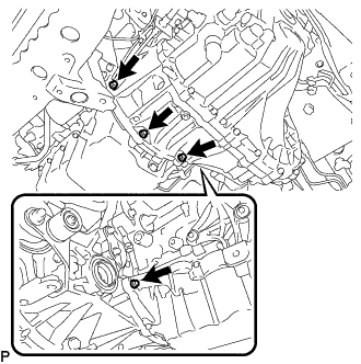
Выверните 4 болта и отсоедините рабочий цилиндр сцепления в сборе и кронштейн гибкого шланга сцепления.
-
-
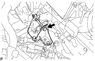
DISCONNECT ENGINE WIRE
-
Remove the bolt and disconnect the ground cable.
-
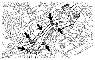
Disconnect the back-up light switch connector, neutral position connector, 2 bolts and engine wire.
-
-
LOOSEN ENGINE AND TRANSAXLE CONNECTING BOLT
-
Manual transaxle upper side:
Using an E14 "TORX" socket wrench, loosen the 2 bolts.
-
Manual transaxle lower side:
Loosen the 4 bolts.
-
Engine mounting insulator side:
Loosen the bolt.
-
-
REMOVE FRONT SUSPENSION MEMBER
-
SUPPORT MANUAL TRANSAXLE ASSEMBLY
-
Support the manual transaxle assembly with a transmission jack and tie down band so that it is stable.
-
-
REMOVE FRONT CROSSMEMBER SUB-ASSEMBLY
-
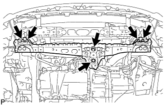
Remove the 6 bolts and front crossmember sub-assembly.
-
-
REMOVE FRONT ENGINE MOUNTING INSULATOR
-
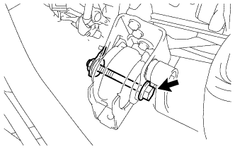
Remove the through bolt, nut and front engine mounting insulator.
-
-
REMOVE MANUAL TRANSAXLE ASSEMBLY
Note
-
As there is very little space around the manual transaxle assembly, be extremely careful that the body, clutch pipe line and radiator cooling fan do not interfere with the manual transaxle assembly when removing the transaxle.
-
When removing the manual transaxle assembly, it is necessary to move the engine assembly and manual transaxle assembly up and down, and back and forth. Therefore, continually confirm that the parts are properly supported and stable while performing this step.
-
Remove the nut and through bolt, and then disconnect the engine mounting insulator LH from the engine mount bracket LH.
-
Lower the transmission jack a little at a time. Slightly tilt the engine assembly and manual transaxle assembly.
Tech Tips
Lower the engine assembly and manual transaxle assembly to a position where the engine mounting insulator LH can be removed.
-
Remove the 4 bolts and engine mount insulator LH.
-
Remove the 4 bolts and engine mounting bracket LH.
Note
Make sure to clean the bolts and bolt holes after removing the transmission.
-
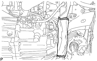
Use a cloth, etc. to protect the clutch pipe line in the area indicated in the illustration.
-
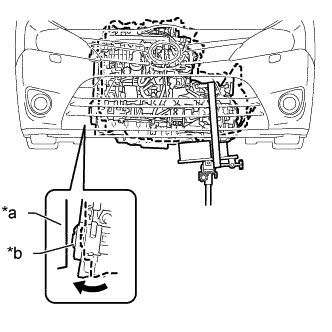
Text in Illustration *a Body *b Crankshaft Damper Sub-assembly Lower the transmission jack a little at a time. Slightly tilt the engine assembly and manual transaxle assembly.
Note
Be careful that the body and crankshaft damper sub-assembly do not interfere with each other.
-
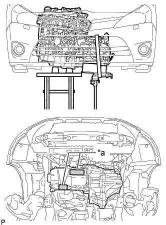
Text in Illustration *a Engine Support Point Support the engine assembly with an engine lifter as shown in the illustration so that it is stable.
-
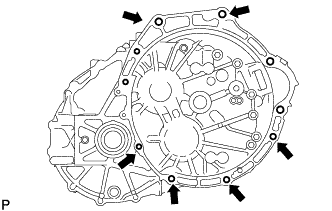
Remove the 6 bolts shown in the illustration.
-
While making sure that the clutch pipe line does not interfere with the manual transaxle assembly, slowly disconnect the manual transaxle assembly from the engine assembly until the input shaft is clear of the diaphragm spring of the clutch cover.
-
Slowly lower the transmission jack and remove the manual transaxle assembly.
-
-
REMOVE REAR ENGINE MOUNTING INSULATOR
Tech Tips
Данную процедуру необходимо выполнять только в том случае, если требуется замена задней подушки опоры двигателя.
-
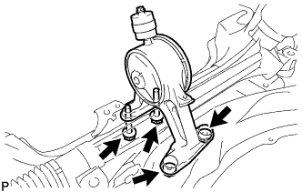
Выверните 2 болта, отверните 2 гайки и снимите заднюю подушку опоры двигателя с поперечины передней подвески.
-
-
REMOVE FRONT ENGINE MOUNTING BRACKET
-
Remove the 4 bolts and front engine mounting bracket.
-
-
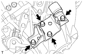
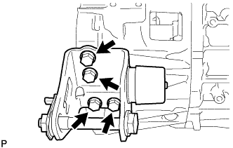
REMOVE REAR ENGINE MOUNTING BRACKET
-
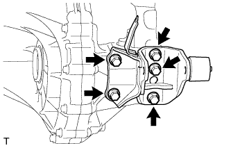
Remove the 5 bolts and rear engine mounting bracket.
-