ТРОСА МЕХАНИЗМА ПЕРЕКЛЮЧЕНИЯ ПЕРЕДАЧ (для моделей с 1WW) СНЯТИЕ
-
PRECAUTION
Note
After turning the ignition switch off, waiting time may be required before disconnecting the cable from the battery terminal. Therefore, make sure to read the disconnecting the cable from the battery terminal notice before proceeding with work Click here
-
DISCONNECT CABLE FROM NEGATIVE BATTERY TERMINAL
Note
When disconnecting the cable, some systems need to be initialized after the cable is reconnected Click here.
-
DISCONNECT CABLE FROM POSITIVE BATTERY TERMINAL
-
REMOVE NO. 1 ENGINE UNDER COVER
-
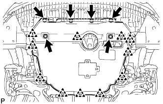
Выверните 6 болтов и снимите 11 фиксаторов.
-
Снимите нижнюю крышку двигателя № 1.
-
-
REMOVE FRONT EXHAUST PIPE ASSEMBLY
-
REMOVE RADIATOR SUPPORT OPENING COVER
-
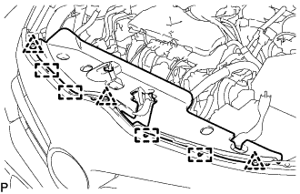
Снимите 3 фиксатора.
-
Открепите 4 крюка и снимите крышку отверстия кронштейна радиатора.
-
-
REMOVE NO. 1 ENGINE COVER
-
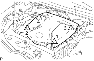
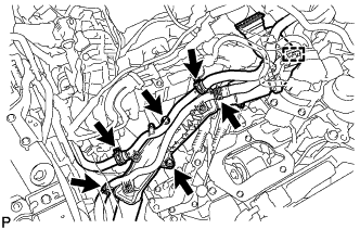
Поднимите крышку двигателя № 1, чтобы освободить 4 фиксатора в порядке, показанном на рисунке, и снимите крышку двигателя № 1.
Note
Попытка одновременно освободить задние и передние фиксаторы может привести к повреждению крышки двигателя № 1.
-
-
DRAIN ENGINE COOLANT
CAUTION:
Не снимайте пробку расширительного бачка радиатора и клапан для выпуска воздуха, пока двигатель и радиатор не остынут. Выброс горячей охлаждающей жидкости и пара под давлением может стать причиной серьезных ожогов.
-
Ослабьте пробку сливного крана радиатора и слейте охлаждающую жидкость двигателя.
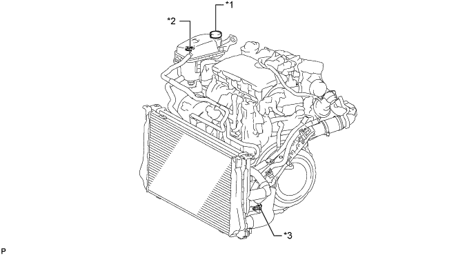
Обозначения на рисунке *1 Пробка расширительного бачка *2 Клапан для выпуска воздуха *3 Пробка сливного крана радиатора - - Tech Tips
Слейте охлаждающую жидкость в резервуар и утилизируйте ее в соответствии с местными требованиями.
-
Снимите пробку расширительного бачка.
-
-
REMOVE BATTERY CLAMP SUB-ASSEMBLY
-
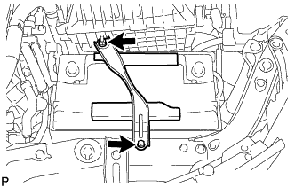
Remove the bolt and loosen the nut.
-
Detach the hook of the battery clamp sub-assembly from the battery carrier, and then remove the battery clamp sub-assembly.
-
-
REMOVE BATTERY INSULATOR
-
REMOVE BATTERY
-
REMOVE BATTERY TRAY
-
REMOVE BATTERY CARRIER
-
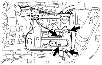
Detach the 2 clamps and disconnect the engine wire.
-
Remove the 4 bolts and battery carrier.
-
-
REMOVE AIR CLEANER CAP SUB-ASSEMBLY WITH AIR CLEANER HOSE ASSEMBLY
-
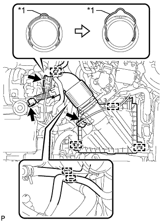
Text in Illustration *1 Retainer Detach the clamp and disconnect the mass air flow meter sub-assembly connector.
-
Detach the clamp and disconnect the vacuum hose from the air cleaner hose assembly.
-
Detach the clamp and disconnect the No. 1 fuel hose from the air cleaner hose assembly.
-
Detach the clamp and disconnect the No. 2 fuel hose from the air cleaner hose assembly.
-
Disconnect the ventilation hose from the cylinder head cover sub-assembly.
-
Release the retainer and disconnect the air cleaner hose assembly from the turbocharger sub-assembly as shown in the illustration.
-
Detach the 2 clamps and remove the air cleaner cap sub-assembly with air cleaner hose assembly.
-
-
REMOVE AIR CLEANER FILTER ELEMENT SUB-ASSEMBLY
-
REMOVE AIR CLEANER CASE SUB-ASSEMBLY
-
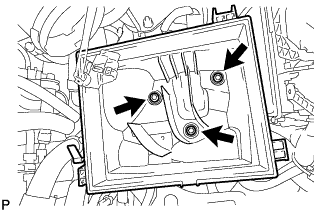
Remove the 3 bolts and air cleaner case sub-assembly.
-
-
DISCONNECT ENGINE WIRE
-
Detach the 2 clamps from the No. 1 air tube assembly.
-
Remove the 2 bolts and disconnect the engine wire from the No. 1 air tube assembly.
-
-
REMOVE NO. 4 WATER BY-PASS HOSE
-
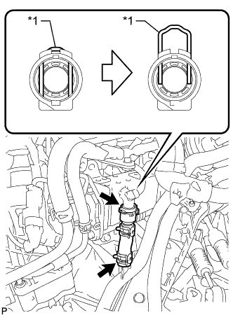
Text in Illustration *1 Retainer Release the retainer and disconnect the No. 4 water by-pass hose from the EGR cooler assembly as shown in the illustration.
-
Slide the clamp and remove the No. 4 water by-pass hose from the No. 2 radiator pipe.
-
-
DISCONNECT COMPRESSOR OUTLET ELBOW
-
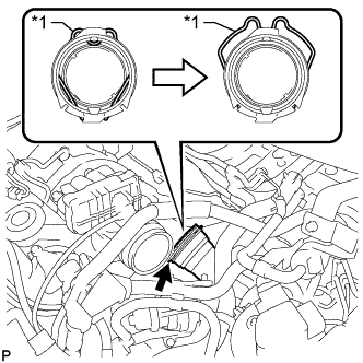
Text in Illustration *1 Retainer Release the retainer and disconnect the compressor outlet elbow from the turbocharger sub-assembly as shown in the illustration.
-
-
DISCONNECT NO. 1 AIR TUBE ASSEMBLY
-
Slide the clamp and disconnect the water by-pass hose assembly from the No. 2 radiator pipe.
-
Slide the clamp and disconnect the radiator hose sub-assembly from the No. 1 radiator pipe.
-
Detach the clamp and disconnect the water hose sub-assembly from the compressor outlet elbow.
-
Slide the clamp and disconnect the water hose sub-assembly from the No. 1 radiator pipe.
-
Slide the clamp and disconnect the outlet heater water hose from the No. 2 radiator pipe.
-
Remove the 2 bolts and disconnect the No. 1 air tube assembly from the manual transaxle assembly.
-
-
REMOVE LOWER NO. 1 INSTRUMENT PANEL FINISH PANEL
-
REMOVE FRONT NO. 1 FLOOR HEAT INSULATOR
-
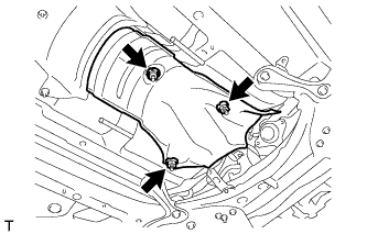
Remove the 3 nuts and front No. 1 floor heat insulator.
-
-
REMOVE TRANSMISSION CONTROL CABLE ASSEMBLY
-
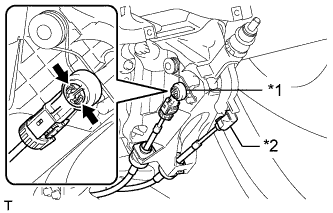
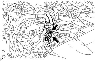
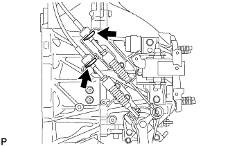
Text in Illustration *1 Control Select Cable *2 Control Shift Cable Disconnect the control shift cable from the shift lever assembly.
-
Pinch the areas indicated by the arrows and disconnect the control select cable.
-
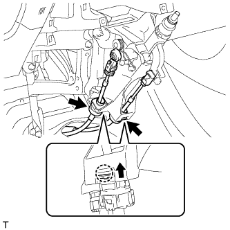
Detach the 2 claws and disconnect the transmission control cable assembly.
-
Remove the 2 clips and disconnect the 2 cables from the manual transaxle assembly.
-
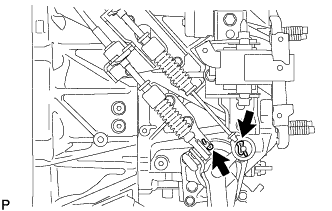
Remove the 2 clips and disconnect the 2 cables from the control cable bracket.
-
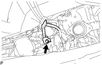
Remove the bolt and detach the bracket of the transmission control cable assembly.
-
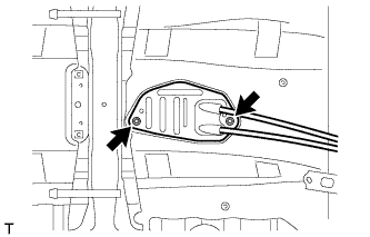
Remove the 2 nuts and detach the grommet of the transmission control cable assembly.
-