БЛОК МЕХАНИЧЕСКОЙ ТРАНСМИССИИ ПОВТОРНАЯ СБОРКА

-
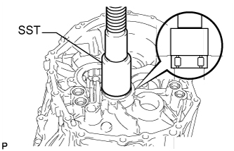
INSTALL SHIFT FORK SHAFT BEARING
-
Using SST and a press, press in 4 new shift fork shaft bearings.
- SST
- 09820-00031
Standard depth 0 to 0.5 mm (0 to 0.0197 in.)
-
-
INSTALL OUTPUT SHAFT COVER
-
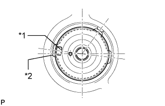
Text in Illustration *1 Protrusion *2 Groove Install the output shaft cover as shown in the illustration.
-
-
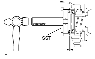
INSTALL NO. 2 OUTPUT SHAFT FRONT BEARING OUTER RACE
-
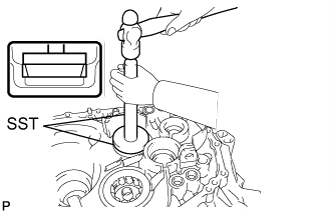
Using SST and a hammer, tap in the No. 2 output shaft front bearing outer race.
- SST
- 09950-70010 ( 09951-07100, 09951-00710 )
-
-
INSTALL OUTPUT SHAFT COVER
-
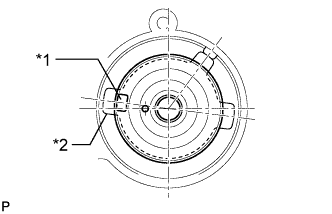
Text in Illustration *1 Protrusion *2 Groove Install the output shaft cover as shown in the illustration.
-
-
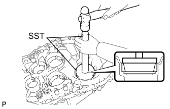
INSTALL OUTPUT SHAFT FRONT BEARING
-
Coat a new front bearing with gear oil. Then, using SST and a press, install the bearing to the front transaxle case.
- SST
- 09223-15020
-
Install the bearing lock plate bolt.
- Torque:
- 11 N*m { 112 kgf*cm, 8 ft.*lbf }
-
-
INSTALL FRONT TRANSAXLE CASE OIL SEAL
-
Using SST and a hammer, install a new front transaxle case oil seal to the front transaxle case.
- SST
- 09950-60010 ( 09951-00580 )
Standard depth 4.4 to 5.0 mm (0.174 to 0.196 in.) -
Coat the lip of the oil seal with MP grease.
-
-
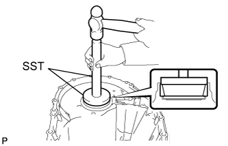
INSTALL INPUT SHAFT FRONT BEARING
-
Coat a new input shaft front bearing with gear oil. Then, using SST and a press, install the bearing to the front transaxle case.
- SST
- 09223-00010
-
Install the bearing lock plate bolt.
- Torque:
- 11 N*m { 112 kgf*cm, 8 ft.*lbf }
-
-
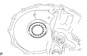
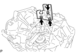
INSTALL INPUT AND OUTPUT SHAFT REAR BEARING SHAFT SNAP RING
-
Using snap ring expander, install the 2 snap rings.
-
-
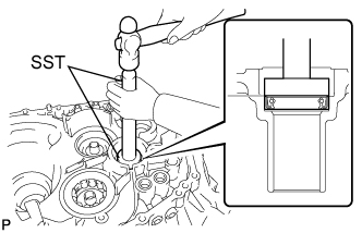
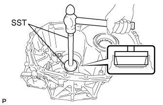
INSTALL SHIFT AND SELECT LEVER SHAFT NEEDLE ROLLER BEARING
-
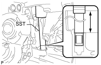
Using SST and a press, press in a new shift and select lever shaft needle roller bearing.
- SST
- 09285-76010
Standard clearance 177.8 to 178.7 mm (7.00 to 7.03 in.)
-
-
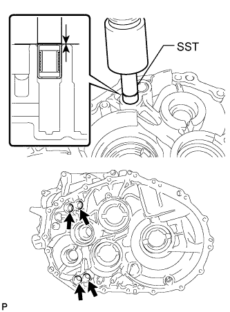
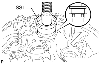
INSTALL SHIFT FORK SHAFT BEARING
-
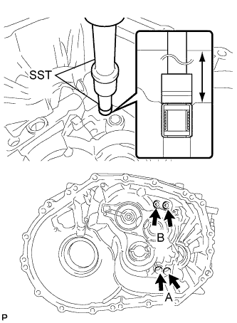
Using SST and a press, press in 4 new shift fork shaft bearings.
- SST
- 09307-12010
- 09820-00031
Standard clearance A 168.2 to 169.3 mm (6.63 to 6.66 in.) Standard clearance B 162.2 to 163.3 mm (6.39 to 6.42 in.)
-
-
INSTALL FRONT DIFFERENTIAL CASE FRONT TAPERED ROLLER BEARING
-
Using SST and a hammer, tap in the front differential case front tapered roller bearing.
- SST
- 09950-70010 ( 09951-00910, 09951-07150 )
-
-
INSTALL FRONT DIFFERENTIAL CASE REAR OUTER RACE BEARING
-
Install the front differential case rear shim into the manual transmission case.
-
Using SST and a hammer, install the front differential case rear outer race bearing.
- SST
- 09950-60010 ( 09951-00910 )
- 09950-70010 ( 09951-07100 )
-
-
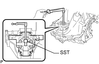
ADJUST DIFFERENTIAL SIDE BEARING PRELOAD
-
Coat the differential case assembly with gear oil and install it to the front transaxle case.
-
Install the manual transmission case to the front transaxle case with the 12 bolts.
- Torque:
- 29 N*m { 300 kgf*cm, 22 ft.*lbf }
-
Install the 6 bolts to the front transaxle case side.
- Torque:
- 29 N*m { 300 kgf*cm, 22 ft.*lbf }
-
Turn the differential case in both directions and make sure it turns smoothly.
-
Text in Illustration *1 Mark Using SST and a torque wrench, measure the starting preload.
- SST
- 09564-33010
New bearing preload 1.00 to 2.49 N*m (10.2 to 25.4 kgf*cm, 8.85 to 22.04 in.*lbf)
-
If the preload is not as specified, replace the shim with one of a different thickness. Use the table below to select a shim which will ensure that the preload is within the specification.
Standard Shim Thickness Mark Specified Condition Mark Specified Condition Mark Specified Condition 0 1.99 to 2.01 mm (0.0783 to 0.0791 in.) 6 2.29 to 2.31 mm (0.0902 to 0.0909 in.) C 2.59 to 2.61 mm (0.1020 to 0.1027 in.) 1 2.04 to 2.06 mm (0.0803 to 0.0811 in.) 7 2.34 to 2.36 mm (0.0921 to 0.0929 in.) D 2.64 to 2.66 mm (0.1040 to 0.1047 in.) 2 2.09 to 2.11 mm (0.0823 to 0.0831 in.) 8 2.39 to 2.41 mm (0.0941 to 0.0949 in.) E 2.69 to 2.71 mm (0.1060 to 0.1066 in.) 3 2.14 to 2.16 mm (0.0843 to 0.0850 in.) 9 2.44 to 2.46 mm (0.0961 to 0.0969 in.) F 2.74 to 2.76 mm (0.1079 to 0.1086 in.) 4 2.19 to 2.21 mm (0.0862 to 0.0870 in.) A 2.49 to 2.51 mm (0.0981 to 0.0988 in.) G 2.79 to 2.81 mm (0.1099 to 0.1106 in.) 5 2.24 to 2.26 mm (0.0882 to 0.0890 in.) B 2.54 to 2.56 mm (0.1000 to 0.1007 in.) H 2.84 to 2.86 mm (0.1119 to 0.1125 in.) -
Remove the 18 bolts and manual transmission case.
-
-
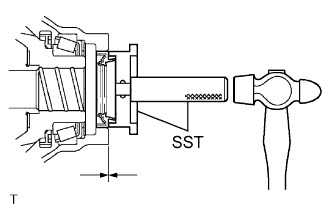
INSTALL NO. 2 OUTPUT SHAFT REAR BEARING OUTER RACE
-
Text in Illustration *1 Mark Install the output shaft rear bearing shim to the manual transmission case.
Tech Tips
When reusing the output shaft rear tapered roller bearing, first install a shim of the same thickness as the original. When installing a new output shaft front bearing, first select and install a shim which is thinner than the original.
-
Using SST and a press, press in the No. 2 output shaft rear bearing outer race.
- SST
- 09950-60010 ( 09951-00650 )
- 09950-70010 ( 09951-07200 )
-
-
ADJUST NO. 2 OUTPUT SHAFT REAR BEARING PRELOAD
-
Install the No. 2 output shaft and differential case to the front transaxle case.
-
Install the manual transmission case to the front transaxle case with the 12 bolts.
- Torque:
- 29 N*m { 300 kgf*cm, 22 ft.*lbf }
-
Install the 6 bolts to the front transaxle case side.
- Torque:
- 29 N*m { 300 kgf*cm, 22 ft.*lbf }
-
Using SST and a torque wrench, measure the No. 2 output shaft rear bearing preload. Subtract the value of the differential side bearing preload from the measured No. 2 output shaft rear bearing preload.
- SST
- 09564-33010
New bearing preload 3.9 to 5.5 N*m (40 to 56 kgf*cm, 35 to 49 in.*lbf) If the preload is not as specified, replace the shim with one of a different thickness. Use the table below to select a shim which will ensure that the preload is within the specification.
Standard Bearing Shim Thickness Mark Specified Condition Mark Specified Condition Mark Specified Condition A 1.79 to 1.81 mm (0.0705 to 0.0713 in.) G 2.09 to 2.11 mm (0.0823 to 0.0831 in.) N 2.39 to 2.41 mm (0.0941 to 0.0949 in.) B 1.84 to 1.86 mm (0.0724 to 0.0732 in.) H 2.14 to 2.16 mm (0.0843 to 0.0850 in.) P 2.44 to 2.46 mm (0.0961 to 0.0969 in.) C 1.89 to 1.91 mm (0.0744 to 0.0752 in.) J 2.19 to 2.21 mm (0.0862 to 0.0870 in.) Q 2.49 to 2.51 mm (0.0980 to 0.0988 in.) D 1.94 to 1.96 mm (0.0764 to 0.0772 in.) K 2.24 to 2.26 mm (0.0882 to 0.0890 in.) R 2.54 to 2.56 mm (0.1000 to 0.1007 in.) E 1.99 to 2.01 mm (0.0783 to 0.0791 in.) L 2.29 to 2.31 mm (0.0902 to 0.0909 in.) S 2.59 to 2.61 mm (0.1020 to 0.1027 in.) F 2.04 to 2.06 mm (0.0803 to 0.0811 in.) M 2.34 to 2.36 mm (0.0921 to 0.0929 in.) T 2.64 to 2.66 mm (0.1040 to 0.1047 in.) -
Remove the 18 bolts and manual transmission case.
-
Remove the output shaft assembly from the front transaxle case.
-
Remove the differential case from the front transaxle case.
-
-
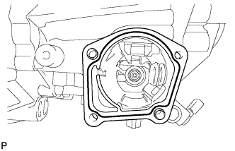
INSTALL TRANSMISSION MAGNET
-
Clean and install the transmission magnet to the front transaxle case.
-
-
INSTALL FRONT DIFFERENTIAL CASE ASSEMBLY
-
Coat the differential case with gear oil, and install it to the front transaxle case.
-
-
INSTALL TRANSMISSION OIL SEPARATOR
-
for Front Transaxle Case Side:
Install the transmission oil separator to the front transaxle case with the 2 bolts.
- Torque:
- 8.5 N*m { 87 kgf*cm, 75 in.*lbf }
-
-
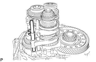
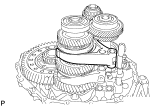
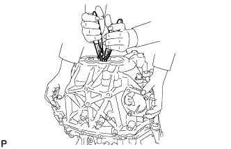
INSTALL INPUT SHAFT, NO. 1 OUTPUT SHAFT AND NO. 2 OUTPUT SHAFT
-
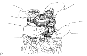
Install the 3 shafts at the same time.
-
-
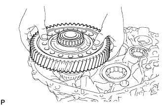
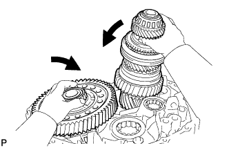
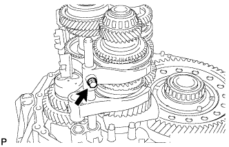
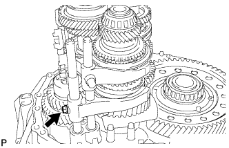
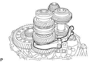
INSTALL REVERSE IDLER GEAR
-
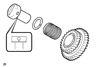
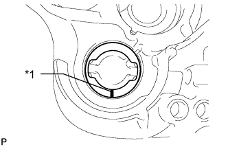
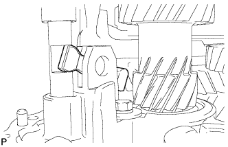
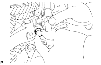
Coat the reverse idler gear, needle roller bearing and reverse idler thrust washer with MP grease, and install them to the reverse idler gear shaft.
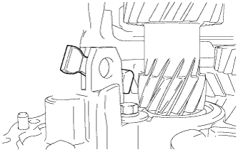
Tech Tips
Make sure that the protruding part of the reverse idler thrust washer fits into the groove of the reverse idler shaft.
-
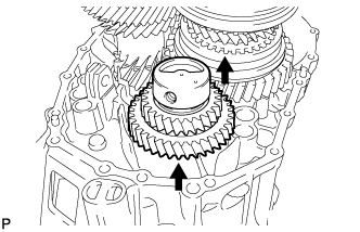
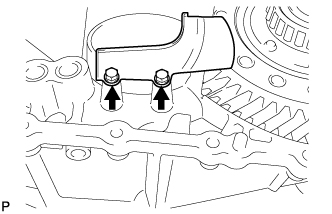
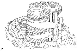
Install the reverse idler gear shaft by sliding and lifting it.
-
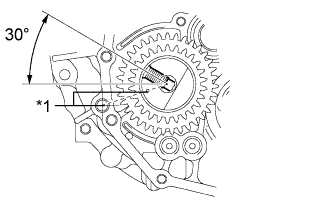
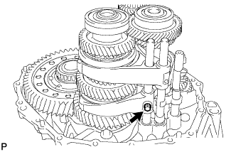
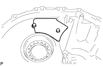
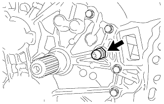
Text in Illustration *1 Alignment Mark Align the mark of the reverse idler gear shaft with the hole of the bolt.
-
-
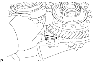
INSTALL REVERSE SHIFT FORK
-
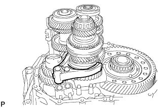
Install the reverse shift fork to the No. 4 hub sleeve.
-
-
INSTALL NO. 3 GEAR SHIFT FORK
-
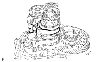
Install the No. 3 gear shift fork to the No. 3 hub sleeve.
-
-
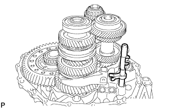
INSTALL 5TH AND 6TH SHIFT FORK SHAFT
-
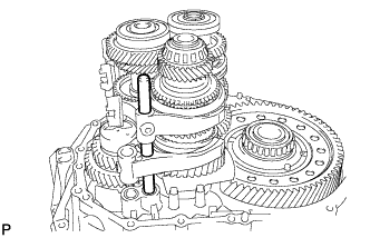
Install the 5th and 6th shift fork shaft to the front transaxle case.
-
Install the bolt to the No. 3 gear shift fork.
- Torque:
- 20 N*m { 200 kgf*cm, 14 ft.*lbf }
-
-
INSTALL REVERSE SHIFT FORK SHAFT
-
Install the reverse shift fork shaft to the front transaxle case.
-
Install the bolt to the reverse gear shift fork.
- Torque:
- 20 N*m { 200 kgf*cm, 14 ft.*lbf }
-
-
INSTALL SHIFT ARM
-
Install the shaft arm to the front transaxle case.
-
-
INSTALL NO. 1 GEAR SHIFT FORK
-
Install the No. 1 gear shift fork to the No. 1 hub sleeve.
-
-
INSTALL NO. 5 GEAR SHIFT FORK SHAFT
-
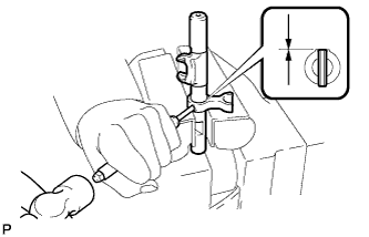
Install the No. 3 gear shift head to the No. 5 gear shift fork shaft.
-
Using a 5 mm pin punch and hammer, tap a new pin into the No. 3 gear shift head.
Standard depth -0.5 to 0.5 mm (-0.0196 to 0.0196 in.) -
Install the No. 5 gear shift fork shaft to the front transaxle case.
-
Connect the shift arm to the No. 5 gear shift fork shaft.
-
Install the shift arm pin to the shift arm.
-
Using a brass bar and hammer, tap a new E-ring to the shift arm pin.
-
-
INSTALL NO. 2 GEAR SHIFT FORK
-
Install the No. 2 gear shift fork to the No. 2 hub sleeve.
-
-
INSTALL 3RD AND 4TH SHIFT FORK SHAFT
-
Install the No. 3 gear shift head to the 3rd and 4th shift fork shaft.
-
Install the 3rd and 4th shift fork shaft to the transmission case.
-
Using a 5 mm pin punch and hammer, tap a new pin into the No. 2 gear shift fork.
Standard depth -0.5 to 0.5 mm (-0.0196 to 0.0196 in.) -
Using a 5 mm pin punch and hammer, tap the pin into the No. 2 gear shift head.
Standard depth -0.5 to 0.5 mm (-0.0196 to 0.0196 in.)
-
-
INSTALL 1ST AND 2ND SHIFT FORK SHAFT
-
Install the 1st and 2nd shift fork shaft to the front transaxle case.
-
Install the bolt to the No. 1 gear shift fork.
- Torque:
- 20 N*m { 200 kgf*cm, 14 ft.*lbf }
-
-
INSTALL TRANSMISSION OIL SEPARATOR
-
for Manual Transmission Case Side:
Install the transmission oil separator to the manual transmission case with the 2 bolts.
- Torque:
- 8.5 N*m { 87 kgf*cm, 75 in.*lbf }
-
-
INSTALL NO. 1 OIL RECEIVER PIPE
-
Install the No. 1 oil receiver pipe to the manual transmission case.
Note
Do not damage the No. 1 oil receiver pipe.
-
-
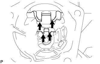
INSTALL MANUAL TRANSMISSION CASE
-
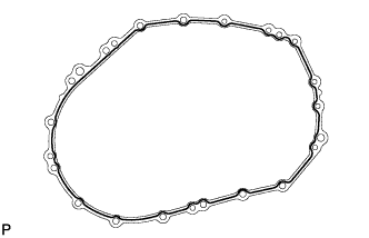
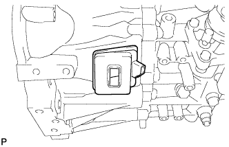
Apply seal packing to the manual transmission case, as shown in the illustration.
Seal packing Toyota Genuine Seal Packing 1281, Three Bond 1281 or equivalent Seal diameter 1.2 mm (0.0472 in.) Note
Assemble parts within 10 minutes of application. Otherwise, the packing (FIPG) material must be removed and reapplied.
-
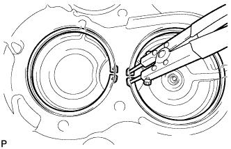
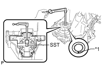
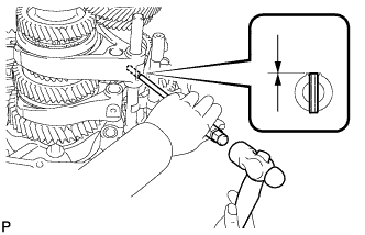
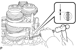
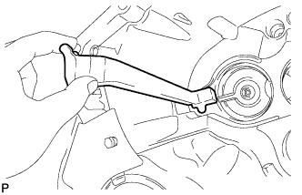
Using 2 pairs of snap ring pliers to keep the snap ring stretched, install the manual transmission case.
-
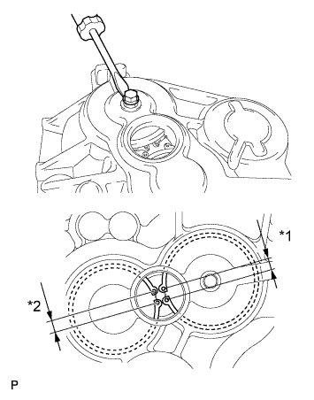
Text in Illustration *1 8.5 mm (0.335 in.) *2 9.3 mm (0.366 in.) Install a bolt to the No. 1 output shaft and lift the No. 1 output shaft from the service hole. Make sure that the snap rings are positioned correctly in the bearing grooves by checking that the distances between the centers of snap ring holes are as shown in the illustration.
-
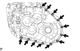
Install the manual transmission case to the front transaxle case with the 12 bolts .
- Torque:
- 29 N*m { 300 kgf*cm, 22 ft.*lbf }
-
Install the 6 bolts to the front transaxle case.
- Torque:
- 29 N*m { 300 kgf*cm, 22 ft.*lbf }
-
-
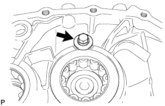
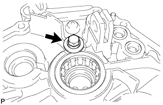
INSTALL REVERSE IDLER GEAR SHAFT BOLT
-
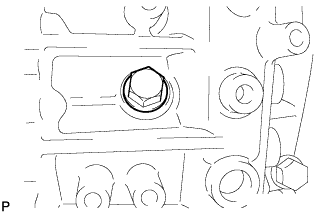
Coat the reverse idler gear shaft bolt with adhesive, and install a new gasket and the shaft bolt.
Adhesive Toyota Genuine Adhesive 1344, Three Bond 1344 or equivalent - Torque:
- 80 N*m { 816 kgf*cm, 59 ft.*lbf }
-
-
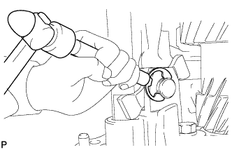
INSTALL BALL
-
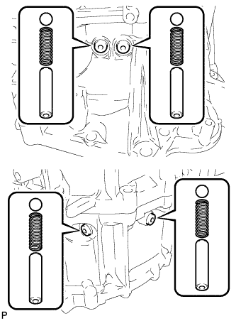
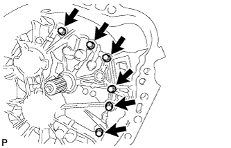
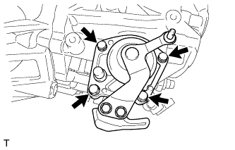
Coat the 4 detent ball plugs with adhesive.
Adhesive Toyota Genuine Adhesive 1344, Three Bond 1344 or equivalent -
Using a 6 mm hexagon wrench, install the 4 balls, 4 springs, 4 spring seats and 4 detent ball plugs .
- Torque:
- 22 N*m { 228 kgf*cm, 17 ft.*lbf }
-
-
INSTALL MANUAL TRANSMISSION CASE PLUG
-
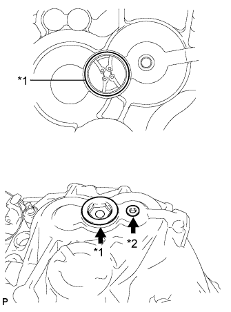
Apply seal packing to the manual transmission case, as shown in the illustration.
Seal packing Toyota Genuine Seal Packing, Three Bond 1207B or equivalent Text in Illustration *1 Seal Packing -
Coat the transmission case plug with adhesive.
Adhesive Toyota Genuine Adhesive 1344, Three Bond 1344 or equivalent -
Install the manual transmission case plug to the manual transmission case.
- Torque:
- for case plug*1
- 55 N*m { 561 kgf*cm, 41 ft.*lbf }
- for case plug*2
- 22 N*m { 228 kgf*cm, 17 ft.*lbf }
-
-
INSTALL O-RING
-
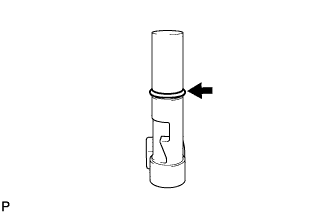
Coat a new O-ring with the grease, and install it to the shift and select pin.
-
-
INSTALL SHIFT AND SELECT PIN
-
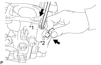
Install the spring.
-
While pressing in the shift and select pin *1 in as far as it will go, push in the shift and select pin *2 to install it.
-
-
INSTALL MANUAL TRANSMISSION FILLER PLUG
-
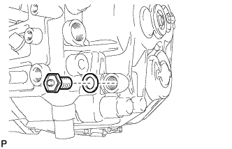
Install a new gasket and the manual transmission filler plug.
- Torque:
- 39 N*m { 400 kgf*cm, 29 ft.*lbf }
-
-
INSTALL DRAIN PLUG
-
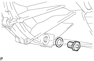
Install a new gasket and the drain plug.
- Torque:
- 39 N*m { 400 kgf*cm, 29 ft.*lbf }
-
-
INSTALL TRANSAXLE CASE OIL SEAL LH
-
Coat the lip of a new oil seal with MP grease.
-
Using SST and a hammer, install the transmission case oil seal.
Standard depth -0.5 to 0.5 mm (-0.0196 to 0.0196 in.) Note
Do not damage the lip of the oil seal.
-
-
INSTALL TRANSAXLE CASE OIL SEAL RH
-
Coat the lip of a new oil seal with MP grease.
-
Using SST and a hammer, install the transaxle case oil seal.
Standard depth -0.5 to 0.5 mm (-0.0196 to 0.0196 in.) Note
Do not damage the lip of the oil seal.
-
-
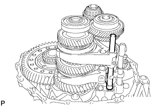
INSTALL SHIFT AND SELECT LEVER ASSEMBLY
-
Align the 4 shift fork shafts as shown in the illustration.
-
Apply seal packing to the transmission case, as shown in the illustration
Seal packing Toyota Genuine Seal Packing, Three Bond 1207B or equivalent -
Coat the 4 bolts with adhesive.
Adhesive Toyota Genuine Adhesive 1344, Three Bond 1344 or equivalent -
Install the shift and select lever shaft to the manual transmission case with the 4 bolts.
- Torque:
- 19 N*m { 190 kgf*cm, 14 ft.*lbf }
-
-
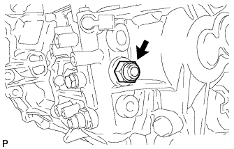
INSTALL SHIFT GATE PIN
-
Coat the shift gate pin with adhesive.
Adhesive Toyota Genuine Adhesive 1344, Three Bond 1344 or equivalent -
Install the shift gate pin to the manual transmission case.
- Torque:
- 30 N*m { 306 kgf*cm, 22 ft.*lbf }
-
-
INSTALL NO. 2 LOCK BALL ASSEMBLY
-
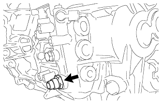
Coat the No. 2 lock ball with adhesive.
Adhesive Toyota Genuine Adhesive 1344, Three Bond 1344 or equivalent -
Install the No. 2 lock ball to the manual transmission case.
- Torque:
- 29 N*m { 300 kgf*cm, 22 ft.*lbf }
-
-
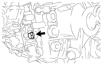
INSTALL NO. 1 LOCK BALL ASSEMBLY
-
Coat the No. 1 lock ball with adhesive.
Adhesive Toyota Genuine Adhesive 1344, Three Bond 1344 or equivalent -
Install the No. 1 lock ball onto the manual transmission case.
- Torque:
- 39 N*m { 400 kgf*cm, 29 ft.*lbf }
-
-
INSTALL BACK-UP LIGHT SWITCH ASSEMBLY
-
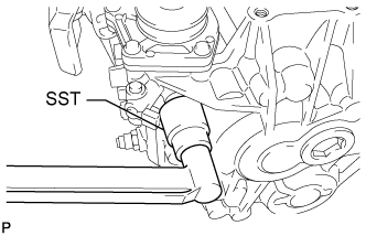
Using SST, install a new gasket and the back-up light switch to the manual transmission case.
- SST
- 09816-30010
- Torque:
- 40 N*m { 410 kgf*cm, 30 ft.*lbf }
-
-
INSTALL SELECTING BELLCRANK ASSEMBLY
-
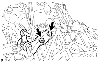
Install the selecting bellcrank to the manual transmission case with the 2 bolts.
- Torque:
- 20 N*m { 204 kgf*cm, 15 ft.*lbf }
-
-
INSTALL FLOOR SHIFT CONTROL LEVER HOUSING SUPPORT BRACKET
-
Install the floor shift control lever housing support bracket to the manual transaxle with the 3 bolts.
- Torque:
- 17 N*m { 173 kgf*cm, 13 ft.*lbf }
-
-
INSTALL RELEASE FORK SUPPORT
-
w/ Precoated part
-
Clean the release fork support installation hole.
-
Install a new release fork support to the manual transaxle assembly.
- Torque:
- 37 N*m { 375 kgf*cm, 27 ft.*lbf }
-
-
w/o Precoated part
-
Install the release fork support to the manual transaxle assembly.
- Torque:
- 47 N*m { 479 kgf*cm, 35 ft.*lbf }
-
-
-
INSTALL CLUTCH RELEASE FORK BOOT
-
Install the clutch release fork boot to the front transaxle case.
-
-
INSTALL CLUTCH RELEASE FORK SUB-ASSEMBLY
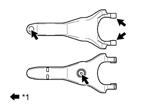
Text in Illustration *1 Release hub grease
-
Apply release hub grease to the release fork where it contacts the release bearing, push rod and release fork support.
Grease Toyota Genuine Release Hub Grease or equivalent -
Install the release fork to the release bearing with the clip.
-
-
INSTALL CLUTCH RELEASE BEARING ASSEMBLY
-
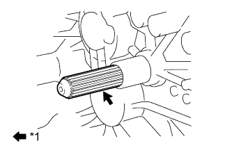
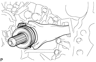
Apply clutch spline grease to the input shaft spline.
Grease Toyota Genuine Clutch Spline Grease or equivalent Text in Illustration *1 Clutch spline grease -
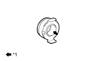
Text in Illustration *1 Release hub grease Apply release hub grease to the inside of the clutch release bearing.
Grease Toyota Genuine Release Hub Grease or equivalent -
Install the clutch release bearing together with the release fork to the manual transaxle assembly.
Note
After the installation, move the fork forward and backward to check that the release bearing slides smoothly.
-