ТРОС МЕХАНИЗМА ПЕРЕКЛЮЧЕНИЯ ПЕРЕДАЧ УСТАНОВКА
-
INSTALL TRANSMISSION CONTROL CABLE ASSEMBLY
-
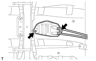
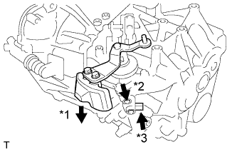
Attach the grommet of the control cable assembly with the 2 nuts.
- Torque:
- 5.0 N*m { 51 kgf*cm, 44 in.*lbf }
-
Attach the bracket of the control cable assembly with the bolt.
- Torque:
- 5.0 N*m { 51 kgf*cm, 44 in.*lbf }
-
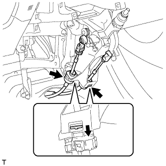
Connect the 2 cables to the control cable bracket with 2 new clips.
-

Connect the 2 cables to the transaxle and install the 2 clips.
-
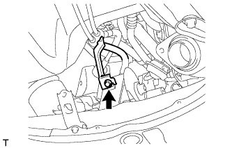
Engage the 2 claws, and install the control cable assembly to the shift lever assembly.
Note
Make sure that the claws are firmly engaged.
-
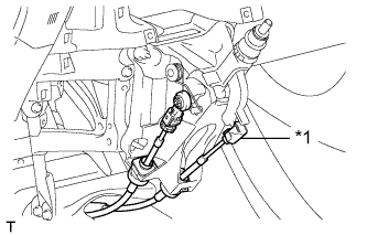
Text in Illustration *1 Select Cable Install the control shift cable to the shift lever assembly.
-
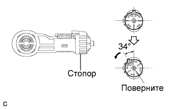
Release the lock of the cable length adjustment structure of the select cable.
-
Turn the stopper.
-
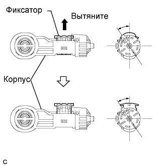
Pull the lock piece outward from the case to release the lock.
-
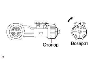
Return the stopper.
-
-
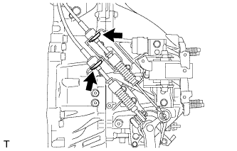
While pressing the shift and select lever shaft (*1) and pin (*2), push in the pin (*3) and check that the shift and select lever shaft is secured at the 1st-2nd gear selected position (the shaft comes to a stop at the position 8 mm (0.315 in.) below the N position).
-
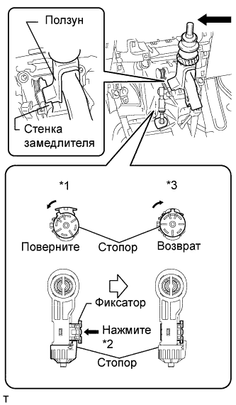
Connect the control select cable to the shift lever assembly.
-
Push the slider against the inhibitor wall.
Note
-
Do not pull up the slider.
-
When adjusting the cable, make sure that the shift lever is not in the 1 or 2.
-
-
Lock the cable length adjustment structure of the select cable.
-
Turn the stopper.*1
-
Push the lock piece into the case.*2
-
Return the stopper to prevent the lock from being released.*3
Note
-
Push the lock piece as far as it will go.
-
Confirm whether the cable length adjustment structure is locked securely.
-
-
-
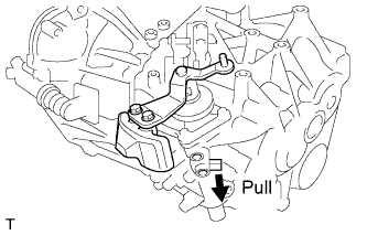
Release the pin that fixes the transmission outer lever.
-
Pull the pin toward the left front side of the vehicle.
-
-
-
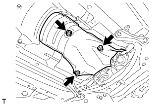
INSTALL FRONT NO. 1 FLOOR HEAT INSULATOR
-
Install the front No. 1 floor heat insulator with the 3 nuts.
- Torque:
- 5.5 N*m { 56 kgf*cm, 49 in.*lbf }
-
-
INSTALL LOWER NO. 1 INSTRUMENT PANEL FINISH PANEL
-
INSTALL AIR CLEANER CASE
-
Установите корпус воздушного фильтра и закрепите его 3 болтами.
- Torque:
- 7,0 Н*м { 71 кгс*см, 62 фунт-сила-дюйма }
-
-
INSTALL AIR CLEANER FILTER ELEMENT SUB-ASSEMBLY
-
INSTALL AIR CLEANER CAP SUB-ASSEMBLY
-
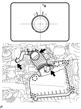
Обозначения на рисунке *a Верх Подсоедините шланг воздушного фильтра к турбонагнетателю и надвиньте хомут, чтобы закрепить его.
Tech Tips
Ориентация шлангового зажима показана на рисунке.
-
Присоедините 4 зажима, чтобы закрепить крышку воздушного фильтра.
-
Подсоедините шланг системы принудительной вентиляции картера к головке блока цилиндров и надвиньте хомут, чтобы закрепить его.
-
Подсоедините разъем датчика массового расхода воздуха и закрепите зажимом.
-
-
INSTALL BATTERY CARRIER
-
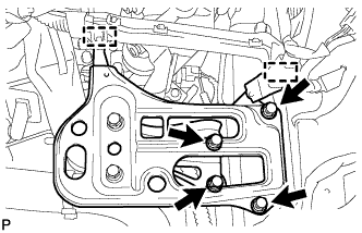
Install the battery carrier with the 4 bolts.
- Torque:
- 19 N*m { 189 kgf*cm, 14 ft.*lbf }
-
Attach the 2 clamps to connect the wire harness.
-
-
INSTALL BATTERY TRAY
-
INSTALL BATTERY
-
INSTALL BATTERY INSULATOR
-
INSTALL BATTERY CLAMP SUB-ASSEMBLY
-
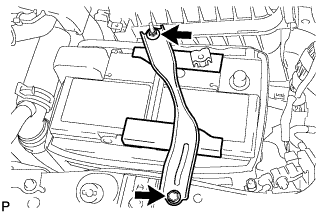
Attach the hook of the battery clamp sub-assembly to the battery carrier.
-
Partially tighten the nut and temporarily install the bolt.
-
Adjust the battery clamp sub-assembly position.
-
Tighten the nut and bolt.
- Torque:
- for bolt
- 17 N*m { 168 kgf*cm, 12 ft.*lbf }
- for nut
- 3.5 N*m { 36 kgf*cm, 31 in.*lbf }
-
-
INSTALL NO. 1 ENGINE COVER
-
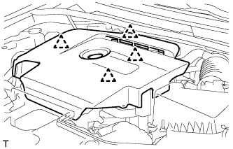
Attach the 4 clips to install the No. 1 engine cover.
-
-
CONNECT CABLE TO POSITIVE BATTERY TERMINAL
-
CONNECT CABLE TO NEGATIVE BATTERY TERMINAL
Note
When disconnecting the cable, some systems need to be initialized after the cable is reconnected Click here.
-
INSTALL FRONT EXHAUST PIPE ASSEMBLY
-
Install the front exhaust pipe assembly Click here.
-