СИСТЕМА АВТОМАТИЧЕСКОЙ ТРАНСМИССИИ, Diagnostic DTC:P0877, P0878
| DTC Code | DTC Name |
|---|---|
| P0877 | Transmission Fluid Pressure Sensor / Switch "D" Circuit Low |
| P0878 | Transmission Fluid Pressure Sensor / Switch "D" Circuit High |
DESCRIPTION
The No. 2 ATF pressure switch is installed in the shift solenoid valve ATF output passage. This switch is used to identify the malfunctioning part when a fail-safe operation is performed. If the shift solenoid valve malfunctions when the ATF pressure switch has a malfunction, a fail-safe operation will be performed. This fail-safe operation is different from the fail-safe operation performed when the shift solenoid valve malfunctions and the ATF pressure switch is normal.
| DTC Code | DTC Detection Condition | Trouble Area |
|---|---|---|
| P0877 | No. 2 ATF pressure switch off state is detected twice when any of the gears from 4th to 6th engages normally (2-trip detection logic). |
|
| P0878 | No. 2 ATF pressure switch on state is detected twice when any of the gears from 1st to 3rd engages normally (2-trip detection logic). |
WIRING DIAGRAM
Refer to DTC P0712 Click here.
INSPECTION PROCEDURE
-
DATA LIST
Tech Tips
Using the intelligent tester to read the Data List allows the values or states of switches, sensors, actuators and other items to be read without removing any parts. This non-intrusive inspection can be very useful because intermittent conditions or signals may be discovered before parts or wiring is disturbed. Reading the Data List information early in troubleshooting is one way to save diagnostic time.
Note
In the table below, the values listed under "Normal Condition" are reference values. Do not depend solely on these reference values when deciding whether a part is faulty or not.
-
Warm up the engine.
-
Turn the ignition switch off.
-
Connect the intelligent tester to the DLC3.
-
Turn the ignition switch to ON.
-
Turn the intelligent tester on.
-
Enter the following menus: Powertrain / ECT / Data List.
-
According to the display on the tester, read the Data List.
ECT Tester Display Measurement Item/Range Normal Condition Diagnostic Note TPS 2 Switch No. 2 ATF pressure switch status/
ON or OFF
-
ON: Gear is 4th, 5th or 6th
-
OFF: Gear is 1st, 2nd or 3rd
- -
-
PROCEDURE
-
CHECK DTC OUTPUT (IN ADDITION TO DTC P0877 OR P0878)
-
Connect the intelligent tester to the DLC3.
-
Turn the ignition switch to ON.
-
Turn the intelligent tester on.
-
Enter the following menus: Powertrain / ECT / DTC.
-
Read the DTCs using the intelligent tester.
Result Result Proceed to Only P0877 is output A Only P0878 is output B P0877 or P0878 and other DTCs are output C
B 
INSPECT TRANSMISSION WIRE (NO. 2 ATF PRESSURE SWITCH) Click here
C 
GO TO DTC CHART Click here
A 
-
-
INSPECT TRANSMISSION WIRE (NO. 2 ATF PRESSURE SWITCH)
-
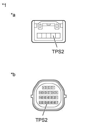
Text in Illustration *1 Transmission Wire *a ATF Temperature Sensor Assembly Side *b TCM Side Disconnect the ATF temperature sensor assembly connector.
-
Remove the TCM.
-
Measure the resistance according to the value(s) in the table below.
Standard Resistance Tester Connection Condition Specified Condition TPS2 ATF temperature sensor assembly side - 20 (TPS2) TCM side Always Below 1 Ω TPS2 ATF temperature sensor assembly side - Body ground (valve body assembly) or any other terminals except 20 (TPS2) TCM side Always 10 kΩ or higher
NG
REPLACE TRANSMISSION WIRE Click here
OK
-
-
REPLACE NO. 2 ATF PRESSURE SWITCH (ATF TEMPERATURE SENSOR ASSEMBLY)
-
Replace the ATF temperature sensor assembly Click here.
NEXT
-
-
CHECK IF DTC OUTPUT RECURS (DTC P0877)
-
Connect the intelligent tester to the DLC3.
-
Turn the ignition switch to ON.
-
Turn the intelligent tester on.
-
Enter the following menus: Powertrain / ECT / DTC / Clear.
Tech Tips
Write down the currently output DTCs before clearing them.
-
Perform the monitor drive pattern Click here.
-
Enter the following menus: Powertrain / ECT / DTC.
-
Read the DTCs using the intelligent tester.
Result Result Proceed to Only P0877 is output A DTCs are not output B
B
END
A 
REPLACE TCM Click here
-
-
INSPECT TRANSMISSION WIRE (NO. 2 ATF PRESSURE SWITCH)
-
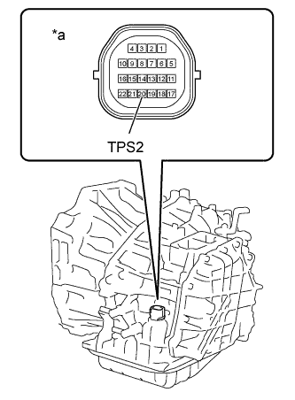
Text in Illustration *a Component without TCM connected
(Transmission Wire)
Remove the TCM.
-
Measure the resistance according to the value(s) in the table below.
Standard Resistance Tester Connection Condition Specified Condition 20 (TPS2) - Body ground Always 10 kΩ or higher
NG
INSPECT NO. 2 ATF PRESSURE SWITCH Click here
OK
REPLACE TCM Click here
-
-
INSPECT NO. 2 ATF PRESSURE SWITCH
-
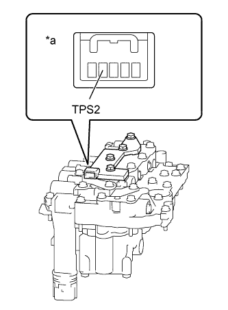
Text in Illustration *a Component without harness connected
(ATF Temperature Sensor Assembly)
Disconnect the ATF temperature sensor assembly connector.
-
Measure the resistance according to the value(s) in the table below.
Standard Resistance Tester Connection Condition Specified Condition TPS2 - Body ground (valve body assembly) or other terminals Always 10 kΩ or higher
NG
REPLACE NO. 2 ATF PRESSURE SWITCH (ATF TEMPERATURE SENSOR ASSEMBLY) Click here
OK
REPLACE TRANSMISSION WIRE Click here
-