СИСТЕМА АВТОМАТИЧЕСКОЙ ТРАНСМИССИИ, Diagnostic DTC:P0741
| DTC Code | DTC Name |
|---|---|
| P0741 | Torque Converter Clutch Solenoid Performance (Shift Solenoid Valve SL) |
DESCRIPTION
The TCM uses signals from the throttle position sensor, air-flow meter, turbine (input) speed sensor, intermediate (counter gear) speed sensor and crankshaft position sensor to help determine the engagement timing of the lock-up clutch. The TCM monitors the engagement of the clutch using the turbine (input) speed sensor, intermediate (counter gear) speed sensor and crankshaft position sensor.
Then the TCM compares the engagement condition of the lock-up clutch with the lock-up schedule in the TCM memory to detect shift solenoid valve SL, valve body and torque converter clutch mechanical problems.
| DTC Code | DTC Detection Condition | Trouble Area |
|---|---|---|
| P0741 | Both conditions are met (2-trip detection logic):
|
|
MONITOR DESCRIPTION
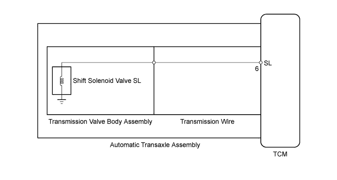
Torque converter lock-up is controlled by the TCM based on the speed sensor NT, speed sensor NC, engine speed, engine load, engine temperature, vehicle speed, ATF temperature and gear selection. The TCM determines the lock-up status of the torque converter by comparing the engine speed (NE) to the input turbine speed (NT). The TCM calculates the actual transmission gear by comparing the input turbine speed (NT) to the counter gear speed (NC). When conditions are appropriate, the TCM requests "lock-up" by applying control voltage to shift solenoid valve SL. When shift solenoid valve SL is turned on, it applies pressure to the lock-up relay valve and locks the torque converter clutch.
If the TCM detects no lock-up after lock-up has been requested or if it detects lock-up when it is not requested, the TCM interprets this as a fault in shift solenoid valve SL or lock-up system performance. The TCM will turn on the MIL and store the DTC.
Tech Tips
Example:
When any of the following is met, the system judges it to be a malfunction.
-
There is a difference in rotation speed between the input side (engine speed) and output side (input turbine speed) of the torque converter when the TCM commands lock-up.
(Engine speed is at least 70 rpm more than the input turbine speed.)
-
There is no difference in rotation speed between the input side (engine speed) and output side (input turbine speed) of the torque converter when the TCM commands lock-up off.
(The difference between the engine speed and input turbine speed is less than 20 rpm.)
WIRING DIAGRAM
INSPECTION PROCEDURE
-
ACTIVE TEST
Tech Tips
Using the intelligent tester to perform Active Tests allows relays, VSVs, actuators and other items to be operated without removing any parts. This non-intrusive functional inspection can be very useful because intermittent operation may be discovered before parts or wiring is disturbed. Performing Active Tests early in troubleshooting is one way to save diagnostic time. Data List information can be displayed while performing Active Tests.
-
Warm up the engine.
-
Turn the ignition switch off.
-
Connect the intelligent tester to the DLC3.
-
Turn the ignition switch to ON.
-
Turn the intelligent tester on.
-
Enter the following menus: Powertrain / ECT / Active Test.
-
According to the display on the tester, perform the Active Test.
ECT Tester Display Test Part Control Range Diagnostic Note Activate the Lock Up Control shift solenoid valve SLU and SL to set the automatic transaxle to lock-up ON or OFF Can be used to check shift solenoid valve SLU and SL operation.
[Vehicle Condition]
-
Vehicle speed: 60 km/h (37 mph) or more
-
-
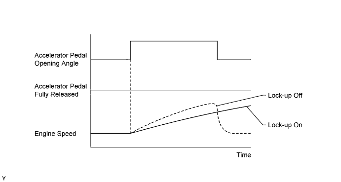
Lightly depress the accelerator pedal and check that the engine speed does not change abruptly.
Tech Tips
-
When changing the accelerator pedal opening angle while driving, if the engine speed does not change abruptly, lock-up is on.
-
When decelerating, slowly release the accelerator pedal, but do not fully release it (fully releasing the pedal will close the throttle valve and lock-up may be turned off).
-
-
PROCEDURE
-
CHECK DTC OUTPUT (IN ADDITION TO DTC P0741)
-
Connect the intelligent tester to the DLC3.
-
Turn the ignition switch to ON.
-
Turn the intelligent tester on.
-
Enter the following menus: Powertrain / ECT / DTC.
-
Read the DTCs using the intelligent tester.
Result Result Proceed to Only P0741 is output A P0741 and other DTCs are output B Tech Tips
If any other codes besides P0741 are output, perform troubleshooting for those DTCs first.
B 
GO TO DTC CHART Click here
A 
-
-
INSPECT TRANSMISSION WIRE (SHIFT SOLENOID VALVE SL)
-
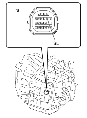
Text in Illustration *a Component without TCM connected
(Transmission Wire)
Remove the TCM.
-
Measure the resistance according to the value(s) in the table below.
Standard Resistance Tester Connection Condition Specified Condition 6 (SL) - Body ground 20°C (68°F) 11 to 15 Ω
NG 
INSPECT SHIFT SOLENOID VALVE SL (RESISTANCE) Click here
OK
-
-
INSPECT SHIFT SOLENOID VALVE SL (OPERATION)
-
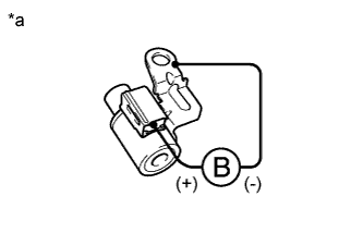
Text in Illustration *a Component without harness connected
(Shift Solenoid Valve SL)
Remove shift solenoid valve SL.
-
Apply 12 V battery voltage to the shift solenoid valve and check that the valve moves and makes an operating noise.
OK Measurement Condition Specified Condition
-
Battery positive (+) → Shift solenoid valve SL connector
-
Battery negative (-) → Shift solenoid valve SL body
Valve moves and makes an operating noise -
NG
REPLACE SHIFT SOLENOID VALVE SL Click here
OK
-
-
INSPECT TRANSMISSION VALVE BODY ASSEMBLY
-
Check the transmission valve body assembly Click here.
OK There are no foreign objects on any valve.
NG
REPAIR OR REPLACE TRANSMISSION VALVE BODY ASSEMBLY Click here
OK
-
-
INSPECT TORQUE CONVERTER CLUTCH ASSEMBLY
-
Check the torque converter clutch assembly Click here.
OK The torque converter clutch operates normally.
NG
REPLACE TORQUE CONVERTER CLUTCH ASSEMBLY Click here
OK 
REPAIR OR REPLACE AUTOMATIC TRANSAXLE ASSEMBLY Click here
-
-
INSPECT SHIFT SOLENOID VALVE SL (RESISTANCE)
-
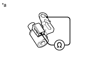
Text in Illustration *a Component without harness connected
(Shift Solenoid Valve SL)
Remove shift solenoid valve SL.
-
Measure the resistance according to the value(s) in the table below.
Standard Resistance Tester Connection Condition Specified Condition Shift solenoid valve SL connector terminal - Shift solenoid valve SL body 20°C (68°F) 11 to 15 Ω
NG
REPLACE SHIFT SOLENOID VALVE SL Click here
OK
REPLACE TRANSMISSION WIRE Click here
-