СИСТЕМА АВТОМАТИЧЕСКОЙ ТРАНСМИССИИ КОНТАКТЫ ЭБУ
-
TCM
Tech Tips
The standard voltage at each TCM terminal is shown in the table below.
In the table, first follow the information under "Condition". Look under "Terminal No. (Symbol)" for the terminals to inspect. The standard voltage between the terminals is shown under "Specified Condition".
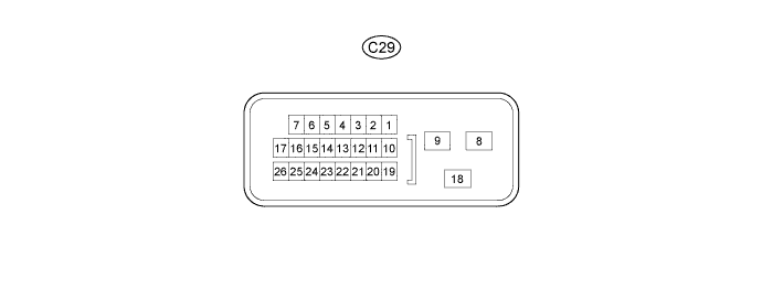
Use the illustration above as a reference for the TCM terminals.
Terminal No. (Symbol) Wiring Color Terminal Description Condition Specified Condition C29-15 (RL) - C29-8 (E1) R - BR R position switch signal Ignition switch ON and shift lever in R 11 to 14 V Ignition switch ON and shift lever in any position except R Below 1 V C29-16 (DL) - C29-8 (E1) G - BR D position switch signal Ignition switch ON and shift lever in D or M 11 to 14 V Ignition switch ON and shift lever in any position except D or M Below 1 V C29-12 (STP) - C29-8 (E1) V - BR Stop light switch signal Brake pedal is depressed 7.5 to 14 V Brake pedal is released Below 1.5 V C29-11 (NSW) - C29-8 (E1) G - BR Park/neutral position switch signal Ignition switch ON and shift lever in P or N Below 2 V Ignition switch ON and shift lever in any position except P or N 11 to 14 V C29-10 (STA) - C29-8 (E1) LG - BR Starter signal Cranking (shift lever in P or N) 6 V or higher Ignition switch ON and shift lever in P or N Below 2 V C29-3 (SPD) - C29-8 (E1) Y - BR Speed signal from combination meter Vehicle speed 20 km/h (12 mph) Pulse generation
(See waveform 1)
C29-1 (BATT) - C29-8 (E1) W - BR Battery (for measuring battery voltage and for TCM memory) Always 11 to 14 V C29-13 (IGSW) - C29-8 (E1) B - BR Ignition switch Ignition switch ON 11 to 14 V C29-18 (+B) - C29-8 (E1) B - BR Power source of TCM Ignition switch ON 11 to 14 V C29-6 (CAN+) - C29-8 (E1) L - BR CAN communication line Ignition switch ON Pulse generation
(See waveform 2)
C29-7 (CAN-) - C29-8 (E1) W - BR CAN communication line Ignition switch ON Pulse generation
(See waveform 3)
-
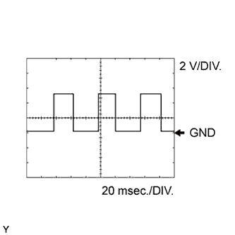
Using an oscilloscope, check waveform 1.
Waveform 1 (reference) Terminal No. (Symbol) Tool Setting Condition C29-3 (SPD) - C29-8 (E1) 2 V/DIV., 20 msec./DIV. Vehicle speed 20 km/h (12 mph) -
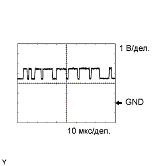
Using an oscilloscope, check waveform 2.
Waveform 2 (reference) Terminal No. (Symbol) Tool Setting Condition C29-6 (CAN+) - C29-8 (E1) 1 V/DIV., 10 μsec./DIV. Ignition switch ON -
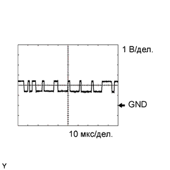
Using an oscilloscope, check waveform 3.
Waveform 3 (reference) Terminal No. (Symbol) Tool Setting Condition C29-7 (CAN-) - C29-8 (E1) 1 V/DIV., 10 μsec./DIV. Ignition switch ON
-
-
ECM
Tech Tips
The standard voltage at each ECM terminal is shown in the table below.
In the table, first follow the information under "Condition". Look under "Terminal No. (Symbol)" for the terminals to inspect. The standard voltage between the terminals is shown under "Specified Condition".
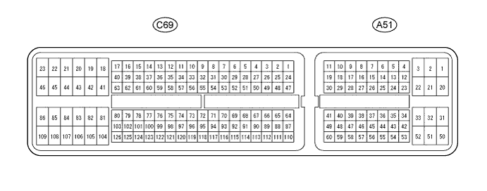
Use the illustration below as a reference for the ECM terminals.
Terminal No. (Symbol) Wiring Color Terminal Description Condition Specified Condition A51-9 (S) - C69-109 (E1) L - BR M position switch signal Ignition switch ON and shift lever in M 11 to 14 V Ignition switch ON and shift lever not in M Below 1 V A51-19 (SFTU) - C69-109 (E1) W - BR Up-shift position switch signal Ignition switch ON and shift lever in M 11 to 14 V
-
Ignition switch ON and shift lever in "+" (up-shift)
-
Ignition switch ON and "+" shift paddle operated (up-shift)
Below 1 V A51-28 (SFTD) - C69-109 (E1) R - BR Down-shift position switch signal Ignition switch ON and shift lever in M 11 to 14 V
-
Ignition switch ON and shift lever in "-" (down-shift)
-
Ignition switch ON and "-" shift paddle operated (down-shift)
Below 1 V A51-36 (PWMS) - C69-109 (E1) R - BR Pattern select switch (SPORT) signal Ignition switch ON and pattern select switch (SPORT) off 11 to 14 V Ignition switch ON and pattern select switch (SPORT) on Below 1.5 V -