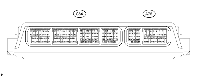
СИСТЕМА КРУИЗ-КОНТРОЛЯ (для моделей с 1WW) КОНТАКТЫ ЭБУ
-
CHECK ECM
-
Disconnect the A76 ECM connector.
Note
After turning the ignition switch off, make sure to wait at least 6 minutes before disconnecting the ECM connector or replacing the ECM.
-
Measure the voltage and resistance according to the value(s) in the table below.
Terminal No. (Symbol) Wiring Color Terminal Description Condition Specified Condition A76-15 (BATT) - Body ground B - Body ground Power source circuit Always 11 to 14 V A76-37 (IGSW) - Body ground B - Body ground IG power source circuit Ignition switch ON 11 to 14 V Ignition switch off Below 1 V A76-10 (ST1-) - Body ground R-W - Body ground Stop light switch signal circuit Ignition switch ON, brake pedal released 11 to 14 V Ignition switch ON, brake pedal depressed Below 1 V A76-48 (STP) - Body ground V - Body ground Stop light switch signal circuit Brake pedal depressed 11 to 14 V Brake pedal released Below 1 V A76-7 (D) - Body ground W - Body ground Clutch switch signal circuit Ignition switch ON, clutch pedal depressed 11 to 14 V Ignition switch ON, clutch pedal released Below 1 V A76-4 (E1) - Body ground W-B - Body ground Ground Always Below 1 Ω If the result is not as specified, there may be a malfunction on the wire harness side.
-
-
CHECK DRIVING SUPPORT ECU

-
Disconnect the H124 driving support ECU connector.
Note
If a load of more than 10 kg (22 lb.) is placed on the connector, it may break. Do not place more load than is necessary on the connector.
-
Measure the voltage and resistance according to the value(s) in the table below.
Terminal No. (Symbol) Wiring Color Terminal Description Condition Specified Condition H124-30 (B) - H124-25 (GND) L - R IG power source circuit Ignition switch ON 11 to 14 V Ignition switch off Below 1 V H124-17 (CA2L) - H124-25 (GND) W - R CAN communication system Ignition switch ON Pulse generation (See waveform 1) H124-27 (STP-) - H124-25 (GND) V - R Stop light switch signal circuit Brake pedal depressed 9 to 14 V Brake pedal released Below 1 V H124-28 (ST1-) - H124-25 (GND) R - R Stop light switch signal input Ignition switch ON, release brake pedal 9 to 14 V Ignition switch ON, depress brake pedal Below 1 V H124-23 (CCS) - H124-25 (GND) SB - R Cruise control switch signal Cruise control main switch on Below 2.5 Ω Cruise control main switch off 1 MΩ or higher +RES switch held on 235 to 245 Ω -SET switch held on 617 to 643 Ω CANCEL switch held on 1509 to 1571 Ω H124-39 (CA2H) - H124-25 (GND) SB - R CAN communication system Ignition switch ON Pulse generation (See waveform 2) H124-25 (GND) - Body ground R - Body ground Ground Always Below 1 Ω If the result is not as specified, there may be a malfunction on the wire harness side.
-
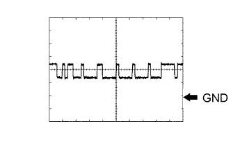
Waveform 1 (CAN communication signal)
Measurement Condition Item Content Tester Connection H124-17 (CA2L) - H124-25 (GND) Tool Setting 1 V/DIV., 10 μsec/DIV. Condition Ignition switch ON -
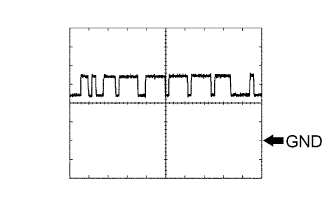
Waveform 2 (CAN communication signal)
Measurement Condition Item Content Tester Connection H124-39 (CA2H) - H124-25 (GND) Tool Setting 1 V/DIV., 10 μsec/DIV. Condition Ignition switch ON
-