СТАРТЕР (для моделей производства VALEO) СНЯТИЕ
-
PRECAUTION
Note
After turning the ignition switch off, waiting time may be required before disconnecting the cable from the battery terminal. Therefore, make sure to read the disconnecting the cable from the battery terminal notice before proceeding with work Click here.
-
DISCONNECT CABLE FROM NEGATIVE BATTERY TERMINAL
Note
When disconnecting the cable, some systems need to be initialized after the cable is reconnected Click here.
-
DISCONNECT CABLE FROM POSITIVE BATTERY TERMINAL
-
REMOVE NO. 1 ENGINE COVER
-
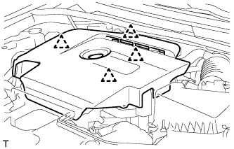
Hold the rear of the No. 1 engine cover and slowly raise it to detach the clip on the rear of the No. 1 engine cover. Continue to raise the No. 1 engine cover to detach the 3 clips on the front and side of the No. 1 engine cover and remove the No. 1 engine cover.
Note
Attempting to disengage both front and rear clips at the same time may cause the No. 1 engine cover to break.
-
-
REMOVE RADIATOR SUPPORT OPENING COVER
-
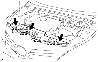
Remove the 3 clips.
-
Detach the 4 hooks and remove the radiator support opening cover.
-
-
REMOVE BATTERY CLAMP SUB-ASSEMBLY
-
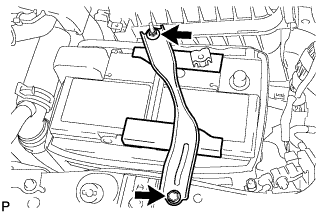
Remove the bolt and loosen the nut.
-
Detach the hook of the battery clamp sub-assembly from the battery carrier, and then remove the battery clamp sub-assembly.
-
-
REMOVE BATTERY INSULATOR
-
REMOVE BATTERY
-
REMOVE BATTERY TRAY
-
REMOVE BATTERY CARRIER
-
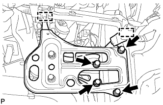
Detach the 2 clamps and disconnect the wire harness.
-
Remove the 4 bolts and battery carrier.
-
-
DISCONNECT NO. 2 VACUUM TRANSMITTING HOSE ASSEMBLY
-

Slide the clamp and disconnect the No. 2 vacuum transmitting hose assembly from the intake manifold.
-
-
REMOVE NO. 3 AIR HOSE
Note
Before installation, remove any oil residue from the inside of pipe and hose.
-
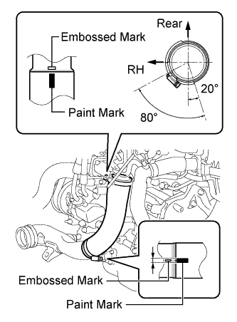
Align the paint mark of the No. 3 air hose with the embossed mark of the diesel throttle body assembly.
-
Align the paint mark of the No. 3 air hose with the embossed mark of the No. 2 air tube.
-
Tighten the clamp of the No. 3 air hose on the diesel throttle body assembly side.
- Torque:
- 6.5 N*m { 66 kgf*cm, 58 in.*lbf }
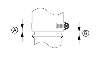
Tech Tips
-
Align the paint mark of the air hose with the embossed mark and push in the air hose so that distance B is 0 to 2 mm (0 to 0.0787 in.).
-
Position the clamp so that distance A is 4 to 9 mm (0.157 to 0.354 in.).
-
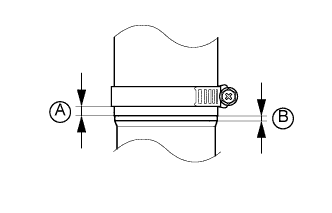
Tighten the clamp of the No. 3 air hose on the No. 2 air tube side.
- Torque:
- 6.5 N*m { 66 kgf*cm, 58 in.*lbf }
Tech Tips
-
Align the paint mark of the air hose with the embossed mark and push in the air hose so that distance B is 0 to 2 mm (0 to 0.0787 in.).
-
Position the clamp so that distance A is 9 to 15 mm (0.354 to 0.591 in.).
-
-
REMOVE STARTER ASSEMBLY
-
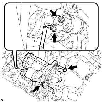
Disconnect the starter connector.
-
Open the terminal cap, remove the nut and disconnect the starter wire.
-
Remove the 2 bolts and starter assembly.
-