-
When replacing the injectors (including shuffling the injectors between the cylinders), common rail, intake manifold or cylinder head, it is necessary to replace the injection pipes with new ones.
-
When replacing the fuel supply pump, common rail, intake manifold or cylinder head, it is necessary to replace the fuel inlet pipe with a new one.
- Click here
INSTALL OIL COOLER ASSEMBLY
-
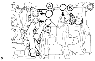
Apply engine oil to the 2 new O-rings labeled B in the illustration.
Note:Do not apply engine oil to the new O-ring labeled A in the illustration.
-
Install 3 new O-rings to the oil cooler bracket.
-
Install the oil cooler with the 5 bolts.
10 N*m 102 kgf*cm 7 ft.*lbf
-
- Click here
INSTALL WATER BY-PASS HOSE
Tip: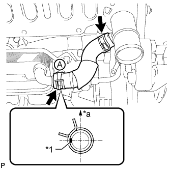
Make sure the claws of hose clamp A are positioned above the paint mark as shown in the illustration.
Table 1. Text in Illustration *1 Paint Mark *a Upper Side - Click here
INSTALL INTAKE MANIFOLD
-
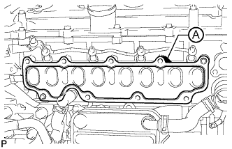
Install a new gasket to the cylinder head.
Tip:Install the gasket with the part labeled A facing the right side of the vehicle as shown in the illustration.
-
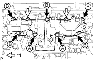
Install the intake manifold with the 7 bolts and 2 nuts.
23 N*m 235 kgf*cm 17 ft.*lbf Table 2. Text in Illustration *1 Nut Standard Bolt Item Length Bolt A 90 mm (3.54 in.) Bolt B 25 mm (0.984 in.)
-
- Click here
CONNECT NO. 2 VACUUM TRANSMITTING HOSE
-
Connect the No. 2 vacuum transmitting hose to the intake manifold.
-
- Click here
INSTALL NO. 2 INTAKE MANIFOLD
-
Install a new gasket and the No. 2 intake manifold with the bolt and 2 nuts.
24 N*m 245 kgf*cm 18 ft.*lbf
-
- Click here
INSTALL ENGINE COVER BRACKET
-
Install the engine cover bracket with the bolt.
20 N*m 204 kgf*cm 15 ft.*lbf
-
- Click here
INSTALL GAS FILTER BRACKET
-
Install the gas filter bracket with the 2 bolts.
8.8 N*m 90 kgf*cm 78 in.*lbf
-
- Click here
INSTALL NO. 1 GAS FILTER
-
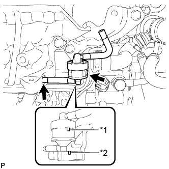
Install the No. 1 gas filter to the gas filter bracket.
Table 3. Text in Illustration *1 Protrusion *2 Groove Note:Make sure the protrusion of the No. 1 gas filter is aligned with the groove of the gas filter bracket.
-
Connect the vacuum hose.
-
- Click here
INSTALL DIESEL TURBO PRESSURE SENSOR
-
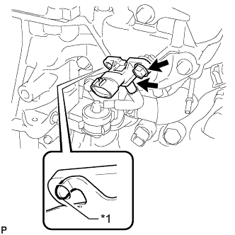
Install the sensor with the bolt.
8.8 N*m 90 kgf*cm 78 in.*lbf Table 4. Text in Illustration *1 Protrusion Note:Make sure the protrusion of the gas filter bracket is inserted into the hole of the sensor.
-
Connect the vacuum hose.
-
- Click here
INSTALL ENGINE OIL LEVEL DIPSTICK GUIDE
-
Install a new O-ring to the engine oil level dipstick guide.
-
Install the engine oil level dipstick guide with the 2 bolts.
24 N*m 245 kgf*cm 18 ft.*lbf -
Connect the connector and attach the wire harness clamp to the engine oil level dipstick guide.
-
Install the engine oil level dipstick.
-
- Click here
INSTALL INTAKE MANIFOLD INSULATOR
-
Install the intake manifold insulator to the intake manifold.
-
- Click here
INSTALL COMMON RAIL ASSEMBLY
-
Install the common rail with the 2 bolts.
21 N*m 209 kgf*cm 15 ft.*lbf -
Using pliers, grip the claws of the clip and slide the clip to connect the fuel hose.
-
- Click here
INSTALL INJECTION PIPE SUB-ASSEMBLY
-
Using a 14 mm union nut wrench, tighten the 4 nuts at the common rail end of the injection pipes.
30 N*m 306 kgf*cm 22 ft.*lbf Note:Use the formula to calculate special torque values for situations where a union nut wrench is combined with a torque wrench (Click here).
-
Using a 14 mm union nut wrench, tighten the 4 nuts at the injector end of the injection pipes.
30 N*m 306 kgf*cm 22 ft.*lbf Note:Use the formula to calculate special torque values for situations where a union nut wrench is combined with a torque wrench (Click here).
-
Install the 4 injection pipe clamps with the 2 bolts.
5.0 N*m 51 kgf*cm 44 in.*lbf
-
- Click here
INSTALL FUEL INLET PIPE SUB-ASSEMBLY
-
Temporarily install the fuel inlet pipe with the 2 clamps and nut.
-
Using a 14 mm union nut wrench, first tighten the nut at the common rail end of the fuel inlet pipe.
30 N*m 306 kgf*cm 22 ft.*lbf Note:Use the formula to calculate special torque values for situations where a union nut wrench is combined with a torque wrench (Click here).
-
Using a 14 mm union nut wrench, tighten the nut at the supply pump end of the fuel inlet pipe.
30 N*m 306 kgf*cm 22 ft.*lbf Note:Use the formula to calculate special torque values for situations where a union nut wrench is combined with a torque wrench (Click here).
-
Tighten the No. 2 injection pipe clamp nut.
5.0 N*m 51 kgf*cm 44 in.*lbf
-
- Click here
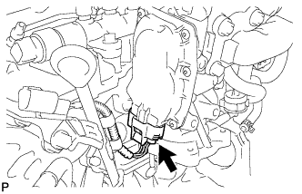
INSTALL ELECTRIC EGR CONTROL VALVE ASSEMBLY
-
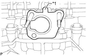
Install a new gasket.
Table 5. Text in Illustration *1 Protrusion Note:Make sure the protrusion of the gasket is facing upward as shown in the illustration.
-
Install the electric EGR control valve.
-
- Click here
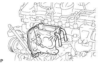
INSTALL NO. 2 EGR PIPE SUB-ASSEMBLY
-
Install 2 new gaskets to the No. 2 EGR pipe and electric EGR control valve.
-
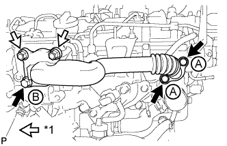
Temporarily install the No. 2 EGR pipe with the 3 bolts and 2 nuts.
Table 6. Text in Illustration *1 Nut Standard Bolt Item Length Bolt A 25 mm (0.984 in.) Bolt B 70 mm (2.76 in.) -
Tighten the 2 bolts labeled A shown in the illustration.
24 N*m 245 kgf*cm 18 ft.*lbf -
Tighten the bolt labeled B and 2 nuts shown in the illustration.
24 N*m 245 kgf*cm 18 ft.*lbf -
Connect the electric EGR control valve connector.
-
-
Click here
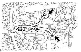
CONNECT NO. 8 WATER BY-PASS HOSE
- Click here
INSTALL NO. 7 WATER BY-PASS HOSE
- Click here
INSTALL EGR VALVE BRACKET
-
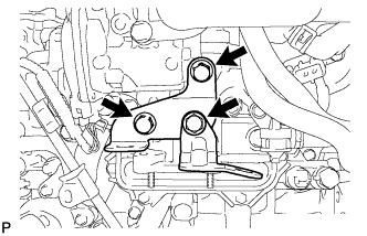
Install the 2 EGR valve brackets with the 3 bolts.
24 N*m 245 kgf*cm 18 ft.*lbf -
Connect the 2 connectors and attach the 2 wire harness clamps.
-
- Click here
CONNECT ENGINE WIRE
-
Connect the engine wire with the bolt and 3 nuts.
8.5 N*m 87 kgf*cm 75 in.*lbf -
Install the wire harness bracket with the bolt.
13 N*m 133 kgf*cm 10 ft.*lbf -
Attach the 2 wire harness clamps.
-
Connect the glow plug wire harness with the nut and grommet.
4.0 N*m 41 kgf*cm 35 in.*lbf -
Connect the pressure discharge valve connector.
-
Connect the fuel pressure sensor connector.
-
- Click here
INSTALL DIESEL THROTTLE BODY ASSEMBLY
-
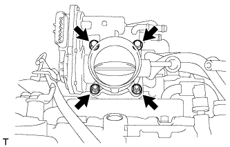
Install a new gasket and the diesel throttle body with the 2 nuts and 2 bolts.
11 N*m 112 kgf*cm 8 ft.*lbf -
Connect the throttle position sensor and throttle motor connector.
-
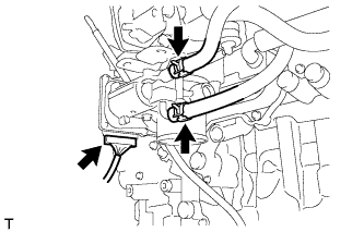
Connect the No. 6 water by-pass hose to the throttle body.
-
Connect the No. 7 water by-pass hose to the throttle body.
-
- Click here
INSTALL NO. 3 AIR HOSE
Note:Before installation, remove any oil residue from the inside of pipe and hose.
-
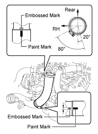
Align the paint mark of the No. 3 air hose with the embossed mark of the throttle body.
-
Align the paint mark of the No. 3 air hose with the embossed mark of the No. 2 air tube.
-
Tighten the clamp of the No. 3 air hose on the diesel throttle body side.
6.5 N*m 66 kgf*cm 58 in.*lbf Tip:
-
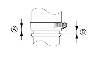
Align the paint mark of the air hose with the embossed mark and push in the air hose so that distance B is 0 to 2 mm (0 to 0.0787 in.).
-
Position the clamp so that distance A is 4 to 9 mm (0.157 to 0.354 in.).
-
-
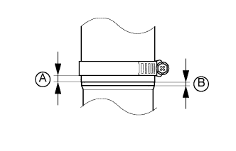
Tighten the clamp of the No. 3 air hose on the No. 2 air tube side.
6.5 N*m 66 kgf*cm 58 in.*lbf Tip:
-
Align the paint mark of the air hose with the embossed mark and push in the air hose so that distance B is 0 to 2 mm (0 to 0.0787 in.).
-
Position the clamp so that distance A is 9 to 15 mm (0.354 to 0.591 in.).
-
-
- Click here
ADD ENGINE OIL
-
Add new engine oil.
Standard Oil Grade Item Oil Grade Oil Viscosity (SAE) for CCo:
Diesel fuel that contains 500 ppm or less of sulfur
ACEA B1, API CF-4 or CF
(You may also use API CE or CD)
- 5W-30
- 10W-30
- 15W-40
- 20W-50
for CCo:
Diesel fuel that contains 50 ppm or less of sulfur
ACEA C2, B1, API CF-4 or CF
(You may also use API CE or CD)
- 0W-30
- 5W-30
- 10W-30
- 15W-40
- 20W-50
for DPF ACEA C2 - 0W-30
- 5W-30
Standard Capacity Item Specified Condition Drain and refill without oil filter change 5.9 liters (6.2 US qts, 5.2 Imp. qts) Drain and refill with oil filter change 6.3 liters (6.7 US qts, 5.5 Imp. qts) Dry fill 7.1 liters (7.5 US qts, 6.2 Imp. qts)
-
- Click here
CONNECT CABLE TO NEGATIVE BATTERY TERMINAL
Note:When disconnecting the cable, some systems need to be initialized after the cable is reconnected (Click here).
- Click here
BLEED AIR FROM FUEL SYSTEM
-
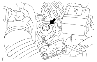
Using the hand pump mounted on the fuel filter cap, bleed the air from the fuel system. Continue pumping until the pump resistance increases.
Note:
-
Hand pump pumping speed: Max. 2 strokes/ sec.
-
The hand pump must be pushed with a full stroke during pumping.
-
When the fuel pressure at the supply pump inlet port reaches a saturated pressure, the hand pump resistance increases.
-
If pumping is interrupted during the air bleeding process, fuel in the fuel line may return to the fuel tank. Continue pumping until the hand pump resistance increases.
-
If the hand pump resistance does not increase despite consecutively pumping 200 times or more, there may be a fuel leak between the fuel tank and fuel filter, the hand pump may be malfunctioning, or the vehicle may have run out of fuel.
-
If air bleeding using the hand pump is incomplete, the common rail pressure does not rise to the pressure range necessary for normal use, and the engine cannot be started.
-
-
Start the engine.
Note:
-
Even if air bleeding using the hand pump has been completed, the starter may need to be cranked for 10 seconds or more to start the engine.
-
Do not crank the engine continuously for more than 20 seconds. The battery may be discharged.
-
Use a fully-charged battery.
-
When the engine can be started, proceed to the next step.
-
If the engine cannot be started, bleed the air again using the hand pump until the hand pump resistance increases (refer to the procedures above). Then start the engine.
-
-
Turn the ignition switch off.
-
Connect the intelligent tester to the DLC3.
-
Turn the ignition switch to ON and turn the intelligent tester on.
-
Clear the DTCs.
-
for DPF: (Click here)
-
for CCo: (Click here)
-
-
Start the engine.*1
-
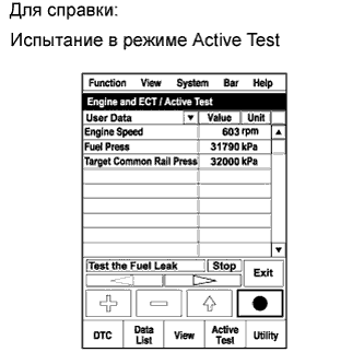
Enter the following menus: Powertrain / Engine and ECT / Active Test / Test the Fuel Leak.*2
-
Perform the following test 5 times with on/off intervals of 10 seconds: Active Test / Test the Fuel Leak.*3
-
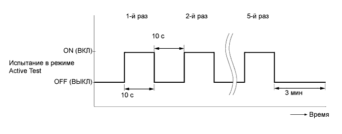
Allow the engine to idle for 3 minutes or more after performing the Active Test for the fifth time.
Tip:When the Active Test "Test the Fuel Leak" is used to change the pump control mode, the actual fuel pressure inside the common rail drops below the target fuel pressure when the Active Test is off, but this is normal and does not indicate a pump malfunction.
-
Enter the following menus: Powertrain / Engine and ECT / DTC.
-
Read Current DTCs.
-
When no DTCs are output, the air bleeding is completed.
-
If any DTCs are output, proceed to the next step.
-
-
Clear the DTCs.
-
for DPF: (Click here)
-
for CCo: (Click here)
-
-
Repeat steps *1 to *3.
-
Enter the following menus: Powertrain / Engine and ECT / DTC.
-
Read Current DTCs.
OK No DTCs are output.
-
- Click here
ADD ENGINE COOLANT
-
Затяните пробку сливного крана радиатора вручную.
-
Затяните пробку сливного крана блока цилиндров.
для типа A 13 Н*м 130 кгс*см 9 фунт-сила-футов для типа B 25 Н*м 255 кгс*см 18 фунт-сила-футов -
Долейте в наливную горловину радиатора фирменную жидкость с увеличенным сроком замены (SLLC) от компании Тойота.
Номинальный объем Параметр / Устройство Заданные условия Для моделей без подогревателя 7,4 литра (7,8 кварты США, 6,5 английской кварты) Для моделей с подогревателем 7,8 литра (8,2 кварты США, 6,9 английской кварты) Tip:Автомобили Toyota первоначально заправляются охлаждающей жидкостью TOYOTA SLLC на заводе. Во избежание повреждения системы охлаждения двигателя или других технических проблем разрешается использовать только охлаждающую жидкость "TOYOTA Super Long Life Coolant" или аналогичную высококачественную охлаждающую жидкость на основе этиленгликоля (а не на силикатной, аминовой, нитритной или борнокислой основе), изготовленную по гибридной технологии органических кислот с длительным сроком годности (охлаждающая жидкость, изготовленная по гибридной технологии органических кислот, состоит из низкофосфатных соединений и органических кислот).
Note:Никогда не используйте воду вместо охлаждающей жидкости.
-
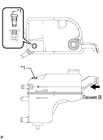
Снимите пробку радиатора и пробку выпуска воздуха, и долейте охлаждающую жидкость до отметки B на расширительном бачке.
Table 7. Обозначения на рисунке *1 Пробка выпуска воздуха -
Несколько раз сожмите рукой входной и выходной патрубки радиатора, а затем проверьте уровень охлаждающей жидкости.
Если уровень охлаждающей жидкости недостаточен, добавьте жидкость.
-
Установите пробку радиатора и пробку выпуска воздуха, а затем надлежащим образом прогрейте двигатель.
2,0 Н*м 20 кгс*см 18 фунт-сила-дюймов -
Выпустите воздух из системы охлаждения.
Note:
-
Перед запуском двигателя установите выключатель системы кондиционирования в положение OFF (ВЫКЛ).
-
Установите температуру кондиционера на уровень MAX (HOT).
-
Установите вентилятор кондиционера в режим Lo.
-
Прогревайте двигатель, пока не откроется термостат. Когда термостат откроется, обеспечьте циркуляцию охлаждающей жидкости в течение нескольких минут.
Tip:Момент открывания термостата можно определить, сжав входной патрубок радиатора рукой и отметив вибрации, когда охлаждающая жидкость двигателя начнет поступать в шланг.
CAUTION:При сжатии патрубка радиатора:
Работайте в защитных перчатках.
Будьте осторожны: патрубки радиатора горячие.
Не прикасайтесь к вентилятору радиатора.
-
После прогрева двигателя дайте ему поработать не менее 7 мин в следующем цикле: на частоте 3000 об/мин в течение 5 с, а затем на частоте вращения холостого хода в течение 45 с (этот цикл следует повторить, по крайней мере, 8 раз).
-
Несколько раз сожмите рукой входной и выходной патрубки радиатора, чтобы удалить воздух из системы.
CAUTION:При сжатии патрубка радиатора:
Работайте в защитных перчатках.
Будьте осторожны: патрубки радиатора горячие.
Не прикасайтесь к вентилятору радиатора.
-
-
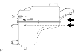
После охлаждения двигателя убедитесь, что уровень охлаждающей жидкости находится между отметками "LOW" и "FULL".
Если уровень охлаждающей жидкости мал, долейте жидкость до отметки FULL на расширительном бачке.
-
- Click here
INSPECT FOR COOLANT LEAK
-
Снимите пробку расширительного бачка радиатора.
CAUTION:Во избежание ожогов не снимайте пробку расширительного бачка радиатора, пока двигатель и радиатор не остынут. Тепловое расширение вызывает выброс из радиатора горячей охлаждающей жидкости и пара.
-
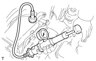
Заполните радиатор охлаждающей жидкостью, а затем подсоедините приспособление для опрессовки системы охлаждения и проверки пробки радиатора.
-
Прогрейте двигатель.
-
С помощью этого приспособления создайте давление 118 кПа (1,2 кгс/см2, 17 фунта на кв. дюйм) и убедитесь, что давление не падает.
Если давление снижается, проверьте на наличие утечек шланги, радиатор и насос системы охлаждения.
Если нет признаков наружной утечки охлаждающей жидкости, проверьте сердцевину отопителя, блок цилиндров и головку блока цилиндров.
-
Установите пробку расширительного бачка радиатора.
-
- Click here
INSPECT FOR OIL LEAK
-
Start the engine. Make sure that there are no oil leaks from the areas that were worked on.
-
- Click here
INSPECT FOR FUEL LEAK
Tip:Using the intelligent tester to perform Active Tests allow relays, VSVs, actuators and other items to be operated without removing any parts. This non-intrusive functional inspection can be very useful because intermittent operation may be discovered before parts or wiring is disturbed. Performing Active Tests early in troubleshooting is one way to save diagnostic time. Data List information can be displayed while performing Active Tests.
-
Perform Active Test.
-
Connect the intelligent tester to the DLC3.
-
Turn the ignition switch to ON.
-
Start the engine.
-
Turn the intelligent tester on.
-
Enter the following menus: Powertrain / Engine / Active Test.
-
Perform the Active Test.
Tester Display Test Part Control Range Diagnostic Notes Test the Fuel Leak Pressurizes common rail internal fuel pressure, and checks for fuel leaks Stop/Start Performs inspection of the high pressure fuel system.
-
Engine Speed: 2050 rpm
-
Fuel Pressure: 172000 kPa
-
Target Common Rail Pressure: 176000 kPa
-
Target Pump SCV Current: 1400 mA
-
MAP: 176 kPa
-
MAF: 39 g/sec.
-
-
-
- Click here
INSPECT ENGINE OIL LEVEL
-
Warm up the engine, stop the engine and wait 5 minutes. The engine oil level should be between the dipstick low level mark and full level mark.
If low, check for leakage and add oil up to the full level mark.
Note:Do not fill engine oil above the full level mark.
-
- Click here
INSTALL NO. 1 ENGINE UNDER COVER
-
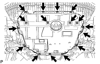
Install the No. 1 engine under cover with the 10 clips and 6 bolts.
-
- Click here
INSTALL RADIATOR SUPPORT OPENING COVER
-
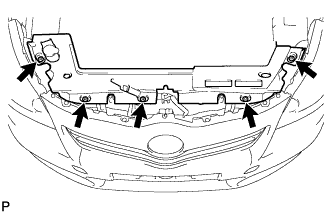
Установите крышку отверстия кронштейна радиатора и закрепите ее 5 фиксаторами.
-
- Click here
INSTALL NO. 1 ENGINE COVER
-
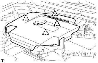
Введите в зацепление 4 фиксатора, чтобы закрепить крышку двигателя № 1.
-
- Click here
INSTALL BATTERY SERVICE HOLE COVER
-
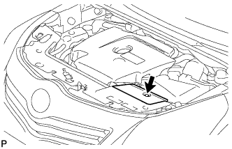
Установите крышку технологического отверстия аккумуляторной батареи и закрепите ее фиксатором.
-