МАСЛЯНЫЙ РАДИАТОР ДВИГАТЕЛЯ СНЯТИЕ
Note
-
When replacing the injectors (including shuffling the injectors between the cylinders), common rail, intake manifold or cylinder head, it is necessary to replace the injection pipes with new ones.
-
When replacing the fuel supply pump, common rail, intake manifold or cylinder head, it is necessary to replace the fuel inlet pipe with a new one.
-
REMOVE NO. 1 ENGINE COVER
-
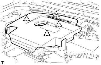
Возьмитесь сзади за крышку двигателя № 1 и медленно поднимите ее, чтобы разъединить задний фиксатор крышки двигателя № 1. Продолжайте поднимать крышку двигателя № 1, чтобы освободить 3 передних и боковых фиксатора крышки двигателя № 1, после чего снимите крышку двигателя № 1.
Note
Попытка освободить задний и передние фиксаторы за один прием может привести к поломке крышки.
-
-
REMOVE RADIATOR SUPPORT OPENING COVER
-
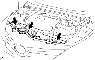
Снимите 3 фиксатора.
-
Открепите 4 крюка и снимите крышку отверстия кронштейна радиатора.
-
-
PRECAUTION
Note
After turning the ignition switch off, waiting time may be required before disconnecting the cable from the battery terminal. Therefore, make sure to read the disconnecting the cable from the battery terminal notice before proceeding with work Click here.
-
DISCONNECT CABLE FROM NEGATIVE BATTERY TERMINAL
Note
When disconnecting the cable, some systems need to be initialized after the cable is reconnected Click here.
-
REMOVE NO. 1 ENGINE UNDER COVER
-
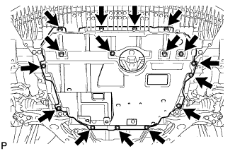
Выверните 6 болтов и снимите 10 фиксаторов.
-
Снимите нижнюю крышку двигателя № 1.
-
-
DRAIN ENGINE OIL
-
Remove the oil filler cap.
-
Remove the oil pan drain plug and gasket, and then drain the engine oil into a container.
-
Install a new gasket and the oil pan drain plug.
- Torque:
- 38 N*m { 387 kgf*cm, 28 ft.*lbf }
-
-
DRAIN ENGINE COOLANT
-
Ослабьте пробку сливного крана радиатора.
Tech Tips
Слейте охлаждающую жидкость в контейнер и утилизируйте ее в соответствии с местными требованиями.
-
Снимите пробку расширительного бачка радиатора.
CAUTION:
Не снимайте пробку расширительного бачка радиатора и пробку выпуска воздуха, пока двигатель и радиатор не остынут. Выброс горячей охлаждающей жидкости и пара под давлением может стать причиной серьезных ожогов.
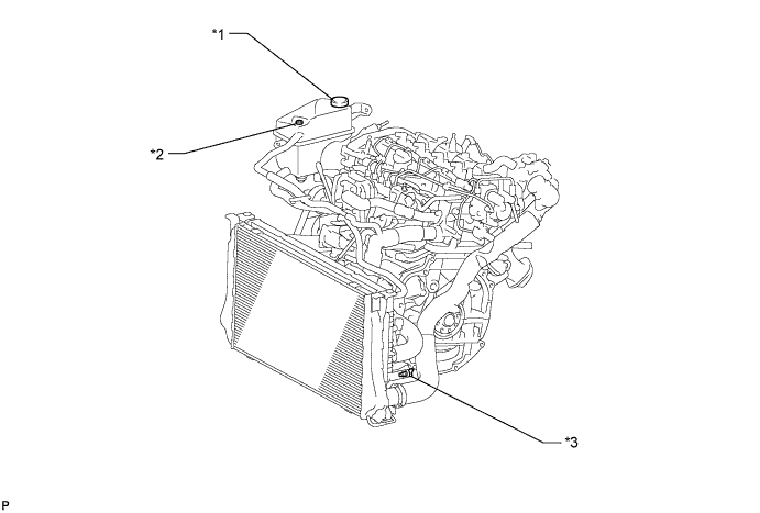
Обозначения на рисунке *1 Пробка бачка радиатора *2 Пробка выпуска воздуха *3 Пробка сливного крана радиатора - -
-
-
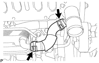
REMOVE NO. 3 AIR HOSE
-
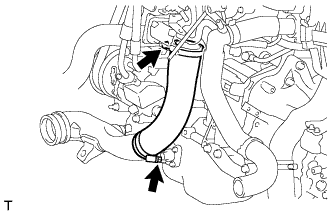
Loosen the 2 hose clamps.
-
Remove the No. 3 air hose from the No. 2 air tube and diesel throttle body assembly.
-
-
REMOVE DIESEL THROTTLE BODY ASSEMBLY
-
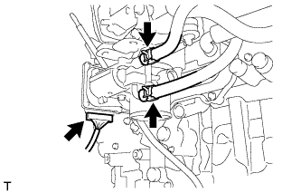
Disconnect the No. 7 water by-pass hose from the diesel throttle body assembly.
-
Disconnect the No. 6 water by-pass hose from the diesel throttle body assembly.
-
Disconnect the throttle position sensor and throttle motor connector.
-
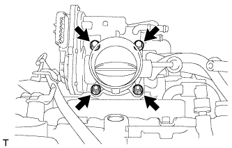
Remove the 2 nuts, 2 bolts, diesel throttle body assembly and gasket.
-
-
DISCONNECT ENGINE WIRE
-
Disconnect the fuel pressure sensor connector and the pressure discharge valve connector.
-
Detach the 2 wire harness clamps.
-
Remove the bolt and wire harness bracket.
-
for DPF:
-
Disconnect the glow plug connector.
-
Disconnect the 3 connectors.
-
Remove the 2 bolts and 5 nuts and disconnect the engine wire.
-
-
for CCo:
Remove the screw grommet and nut, and disconnect the glow plug wire harness.
-
Remove the screw grommet and nut, and disconnect the glow plug wire harness.
-
Remove the bolt and 3 nuts, and disconnect the engine wire.
-
-
-
REMOVE EGR VALVE BRACKET
-
Отсоедините 2 разъема и открепите 2 зажима жгута проводов.
-
Выверните 3 болта и снимите 2 кронштейна клапана РОГ.
-
-
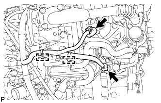
REMOVE NO. 7 WATER BY-PASS HOSE
-
Slide the clamp and remove the No. 7 water by-pass hose from the electric EGR control valve assembly.
-
-
DISCONNECT NO. 8 WATER BY-PASS HOSE
-
Сдвиньте хомут и отсоедините перепускной шланг охлаждающей жидкости № 8 от электрического клапана РОГ.
-
-
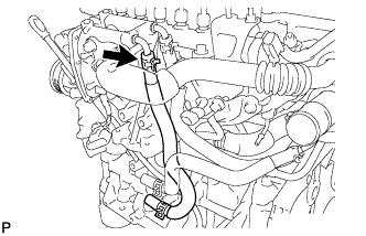
REMOVE NO. 2 EGR PIPE SUB-ASSEMBLY
-
Отсоедините разъем электрического клапана управления РОГ.
-
Обозначения на рисунке *1 Гайка Выверните 3 болта, отверните 2 гайки и снимите трубу РОГ № 2 в сборе и 2 прокладки.
-
-
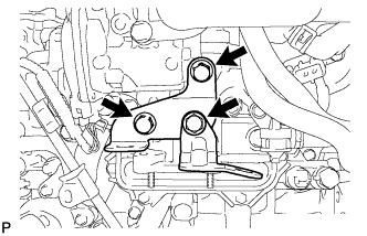
REMOVE ELECTRIC EGR CONTROL VALVE ASSEMBLY
-
Снимите электрический клапан РОГ в сборе и прокладку.
-
-
REMOVE FUEL INLET PIPE SUB-ASSEMBLY
Note
After removing the fuel inlet pipe, cover the common rail and supply pump with electrical tape to prevent dirt from entering them.
-
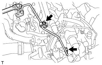
Remove the nut and 2 No. 2 injection pipe clamps.
-
Using a 14 mm union nut wrench, remove the fuel inlet pipe sub-assembly.
-
-
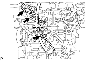
REMOVE INJECTION PIPE SUB-ASSEMBLY
Note
After removing the injection pipe, to prevent dirt or foreign objects from entering the pipe inlet, cover the common rail with electrical tape. Also protect the injector inlets with electrical tape or plastic bags.
-
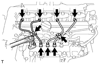
Remove the 2 bolts and 4 No. 2 injection pipe clamps.
-
Using a 14 mm union nut wrench, loosen the 4 union nuts at the common rail assembly end of the injection pipes.
-
Using a 14 mm union nut wrench, loosen the 4 union nuts at the injector assembly end of the injection pipes.
-
Remove the 4 injection pipes.
-
-
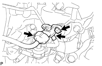
REMOVE COMMON RAIL ASSEMBLY
-
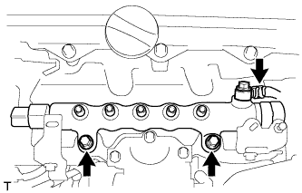
Using pliers, grip the claws of the clip and slide the clip to disconnect the No. 4 fuel hose from the common rail assembly.
-
Remove the 2 bolts and common rail assembly.
-
-
REMOVE INTAKE MANIFOLD INSULATOR
-
Remove the intake manifold insulator from the intake manifold.
-
-
REMOVE ENGINE OIL LEVEL DIPSTICK GUIDE
-
Remove the engine oil level dipstick.
-
Disconnect the connector and detach the wire harness clamp from the engine oil level dipstick guide.
-
Remove the 2 bolts and engine oil level dipstick guide.
-
Remove the O-ring from the engine oil level dipstick guide.
-
-
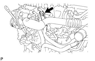
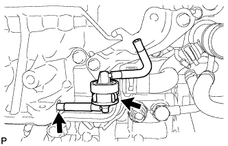
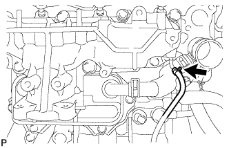
REMOVE DIESEL TURBO PRESSURE SENSOR
-
Disconnect the vacuum hose.
-
Disconnect the sensor connector.
-
Remove the bolt and sensor.
-
-
REMOVE NO. 1 GAS FILTER
-
Disconnect the vacuum hose.
-
Remove the No. 1 gas filter from the gas filter bracket.
-
-
REMOVE GAS FILTER BRACKET
-
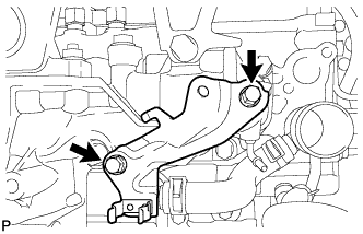
Remove the 2 bolts and gas filter bracket.
-
-
REMOVE ENGINE COVER BRACKET
-
Remove the bolt and engine cover bracket.
-
-
REMOVE NO. 2 INTAKE MANIFOLD
-
Remove the bolt, 2 nuts, No. 2 intake manifold and gasket.
-
-
DISCONNECT NO. 2 VACUUM TRANSMITTING HOSE
-
Slide the clamp and disconnect the No. 2 vacuum transmitting hose from the intake manifold.
-
-
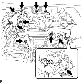
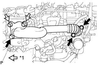
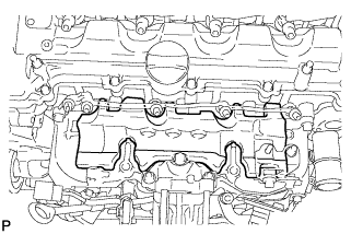
REMOVE INTAKE MANIFOLD
-
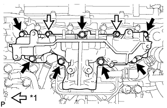
Text in Illustration *1 Nut Remove the 7 bolts, 2 nuts, intake manifold and gasket.
-
Remove the gasket from the cylinder head.
-
-
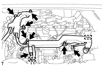
REMOVE WATER BY-PASS HOSE
-
Slide the 2 clamps and remove the water by-pass hose from the water outlet and oil cooler assembly.
-
-
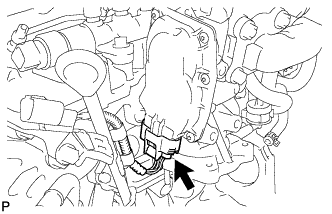
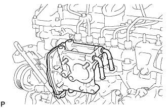
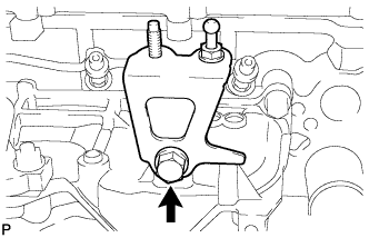
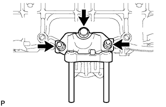
REMOVE OIL COOLER ASSEMBLY
-
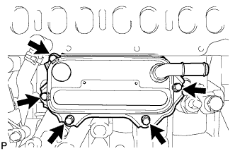
Remove the 5 bolts and oil cooler assembly.
-
for CCo:
Remove the 3 O-rings from the No. 1 oil cooler bracket.
-
for DPF:
Remove the 3 gaskets from the No. 1 oil cooler bracket.
-