ВЫПУСКНОЙ КОЛЛЕКТОР С ТУРБОНАГНЕТАТЕЛЕМ УСТАНОВКА
-
INSTALL EXHAUST MANIFOLD
-
Install 2 new gaskets to the cylinder head sub-assembly.
-
Temporarily install the exhaust manifold with the 8 nuts.
-
Step 1:
Tighten the 8 nuts of the exhaust manifold.
- Torque:
- 11 N*m { 112 kgf*cm, 8 ft.*lbf }
-
Step 2:
Tighten the 8 nuts again.
- Torque:
- 13 N*m { 133 kgf*cm, 10 ft.*lbf }
-
-
INSTALL EGR COOLER ASSEMBLY WITH EGR VALVE ASSEMBLY
-
Install a new water pipe to the EGR cooler assembly.
-
Install a new gasket to the No. 2 EGR pipe sub-assembly.
Tech Tips
Make sure that the claw of the gasket faces the No. 2 EGR pipe sub-assembly.
-
Temporarily install the EGR cooler assembly with EGR valve assembly with the 7 bolts.
-
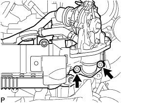
Using a T45 "TORX" socket wrench, tighten the 2 bolts.
- Torque:
- 5.0 N*m { 51 kgf*cm, 44 in.*lbf }
-
Loosen the 2 bolts 90°.
-
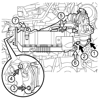
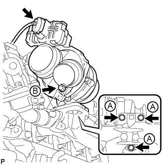
Tighten the 7 bolts labeled A, B and C, and then 2 nuts in the order shown in the illustration.
- Torque:
- for bolt A
- 13 N*m { 133 kgf*cm, 10 ft.*lbf }
- for bolt B
- 19 N*m { 194 kgf*cm, 14 ft.*lbf }
- for bolt C
- 8.0 N*m { 82 kgf*cm, 71 in.*lbf }
Text in Illustration 
Bolt A 
Bolt B 
Bolt C Tech Tips
-
When tightening the bolts labeled A, use a T45 "TORX" socket wrench.
-
When tightening the bolts labeled B, use a 6 mm hexagon wrench.
-
Connect the vacuum hoses to the EGR cooler assembly.
-
Connect the hose clamp to the EGR cooler hose.
-
Attach the clamp and connect the engine wire to the EGR valve assembly.
-
Connect the EGR valve assembly connector.
-
-
INSTALL NO. 1 EXHAUST MANIFOLD HEAT INSULATOR
-
Install the No. 1 exhaust manifold heat insulator with the 2 bolts.
- Torque:
- 8.0 N*m { 82 kgf*cm, 71 in.*lbf }
-
Attach the 2 clamps and connect the engine wire.
-
Attach the 2 clamps and connect the air fuel ratio sensor.
-
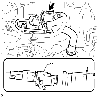
Text in Illustration *1 Air Fuel Ratio Sensor *2 Bracket *a 1.5 mm (0.0591 in.) or less Lower the air fuel ratio sensor connector to the position shown in the illustration and connect the air fuel ratio sensor connector.
-
-
CONNECT FUEL FEED PIPE SUB-ASSEMBLY
-
Connect the fuel feed pipe sub-assembly to the fuel pipe clamp.
-
Connect the vacuum hose to the No. 2 fuel hose.
-
Connect the fuel feed pipe sub-assembly with the 2 bolts.
- Torque:
- 8.0 N*m { 82 kgf*cm, 71 in.*lbf }
-
Attach the 2 clamps and connect the engine wire.
-
-
CONNECT NO. 1 AIR TUBE ASSEMBLY
-
Connect the No. 1 air tube assembly to the manual transaxle assembly with the 2 bolts.
- Torque:
- 20 N*m { 204 kgf*cm, 15 ft.*lbf }
-
Connect the outlet heater water hose to the No. 2 radiator pipe, and slide the clamp to secure the hose.
-
Connect the water hose sub-assembly to the No. 1 radiator pipe, and slide the clamp to secure the hose.
-
Attach the clamp and connect the water hose sub-assembly to the compressor outlet elbow.
-
Connect the water by-pass hose assembly to the No. 2 radiator pipe, and slide the clamp to secure the hose.
-
Connect the radiator hose sub-assembly to the No. 1 radiator pipe, and slide the clamp to secure the hose.
-
-
INSTALL NO. 4 WATER BY-PASS HOSE
-
Text in Illustration *1 Retainer Install the No. 4 water by-pass hose to the No. 2 radiator pipe, and slide the clamp to secure the hose.
-
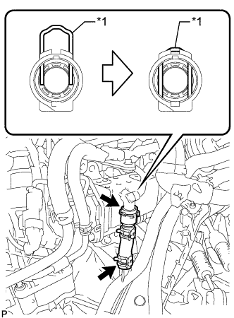
Connect the No. 4 water by-pass hose to the EGR cooler assembly and lock the retainer as shown in the illustration.
-
-
CONNECT ENGINE WIRE
-
Connect the engine wire to the No. 1 air tube assembly with the 2 bolts.
- Torque:
- 8.4 N*m { 86 kgf*cm, 74 in.*lbf }
-
Attach the 2 clamps to the No. 1 air tube assembly.
-
-
INSTALL TURBOCHARGER SUB-ASSEMBLY
-
Temporarily install a new gasket, the turbocharger sub-assembly and the 3 bolts labeled A.
-
Temporarily install the bolt labeled B.
-
Tighten the 4 bolts.
- Torque:
- for bolt A
- 25 N*m { 255 kgf*cm, 18 ft.*lbf }
- for bolt B
- 10 N*m { 102 kgf*cm, 7 ft.*lbf }
-
Connect the connector to the turbocharger sub-assembly.
-
-
INSTALL NO. 1 EXHAUST MANIFOLD PIPE
-
Temporarily install the No. 1 exhaust manifold pipe with the bolt.
-
Temporarily install 2 new gaskets with the union bolt.
-
Tighten the bolt and union bolt.
- Torque:
- for bolt
- 8.0 N*m { 82 kgf*cm, 70 in.*lbf }
- for union bolt
- 35 N*m { 357 kgf*cm, 26 ft.*lbf }
-
Connect the exhaust manifold pressure sensor connector.
-
-
CONNECT NO. 1 TURBO OIL PIPE
-
Connect the No. 1 turbo oil pipe and 2 new gaskets with the union bolt.
- Torque:
- 22 N*m { 224 kgf*cm, 16 ft.*lbf }
-
-
INSTALL TURBO OIL OUTLET PIPE
-
Install a new O-ring to the turbo oil outlet pipe.
-
Install a new gasket and the turbo oil outlet pipe with the 3 bolts.
- Torque:
- 10 N*m { 102 kgf*cm, 7 ft.*lbf }
-
-
CONNECT COMPRESSOR OUTLET ELBOW
-
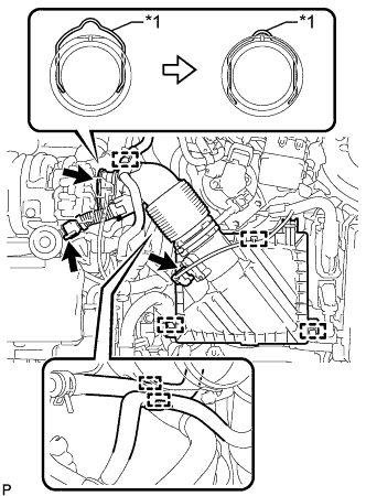
Text in Illustration *1 Retainer Connect the compressor outlet elbow to the turbocharger sub-assembly and lock the retainer as shown in the illustration.
-
-
INSTALL AIR CLEANER CASE SUB-ASSEMBLY
-
Install the air cleaner case sub-assembly with the 3 bolts.
- Torque:
- 7.0 N*m { 71 kgf*cm, 62 in.*lbf }
-
-
INSTALL AIR CLEANER FILTER ELEMENT SUB-ASSEMBLY
-
INSTALL AIR CLEANER CAP SUB-ASSEMBLY WITH AIR CLEANER HOSE ASSEMBLY
-
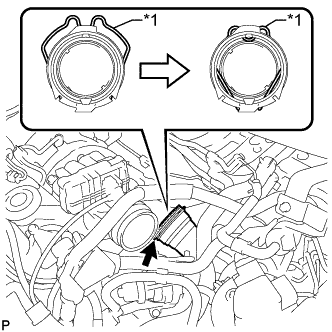
Text in Illustration *1 Retainer Connect the air cleaner hose assembly to the turbocharger sub-assembly and lock the retainer as shown in the illustration.
-
Attach the 2 clamps to install the air cleaner cap sub-assembly.
-
Connect the ventilation hose to the cylinder head cover sub-assembly.
-
Attach the clamp and connect the No. 2 fuel hose to the air cleaner hose assembly.
-
Attach the clamp and connect the No. 1 fuel hose to the air cleaner hose assembly.
-
Attach the clamp and connect the vacuum hose to the air cleaner hose assembly.
-
Attach the clamp and connect the mass air flow meter sub-assembly connector.
-
-
INSTALL BATTERY CARRIER
-
Install the battery carrier with the 4 bolts.
- Torque:
- 19 N*m { 189 kgf*cm, 14 ft.*lbf }
-
Attach the 2 clamps to connect the engine wire.
-
-
INSTALL BATTERY TRAY
-
INSTALL BATTERY
-
INSTALL BATTERY INSULATOR
-
INSTALL BATTERY CLAMP SUB-ASSEMBLY
-
Attach the hook of the battery clamp sub-assembly to the battery carrier.
-
Partially tighten the nut and temporarily install the bolt.
-
Adjust the battery clamp sub-assembly position.
-
Tighten the nut and bolt.
- Torque:
- for bolt
- 17 N*m { 168 kgf*cm, 12 ft.*lbf }
- for nut
- 3.5 N*m { 36 kgf*cm, 31 in.*lbf }
-
-
INSTALL RADIATOR SUPPORT OPENING COVER
-
Установите крышку отверстия кронштейна радиатора и введите в зацепление 4 крюка.
-
Установите 3 фиксатора.
-
-
INSTALL EXHAUST MANIFOLD CONVERTER SUB-ASSEMBLY
-
CONNECT CABLE TO POSITIVE BATTERY TERMINAL
-
CONNECT CABLE TO NEGATIVE BATTERY TERMINAL
Note
When disconnecting the cable, some systems need to be initialized after the cable is reconnected Click here.
-
ADD ENGINE COOLANT
CAUTION:
Не снимайте пробку расширительного бачка радиатора и клапан для выпуска воздуха, пока двигатель и радиатор не остынут. Выброс горячей охлаждающей жидкости и пара под давлением может стать причиной серьезных ожогов.
-
Затяните пробку сливного крана радиатора вручную.
-
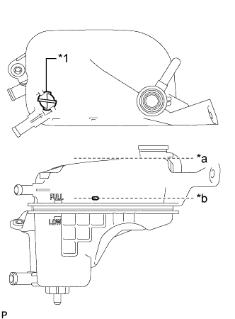
Обозначения на рисунке *1 Клапан для выпуска воздуха *a Горловина расширительного бачка радиатора в сборе *b Верхняя отметка заливки Снимите клапан для выпуска воздуха.
-
Долейте охлаждающую жидкость двигателя до верхней отметки расширительного бачка радиатора.
Номинальный объем Параметр / Устройство Заданные условия Для моделей без дополнительного подогревателя пламенного типа 7,0 л (7,4 кварты США, 6,2 англ. кварты) Для моделей с дополнительным подогревателем пламенного типа 7,3 л (7,7 кварты США, 6,4 англ. кварты) Note
Никогда не используйте воду вместо охлаждающей жидкости.
Tech Tips
Компания Toyota рекомендует использование одобренной охлаждающей жидкости "Toyota Premium Long Life Coolant for 1WW/2WW engines" или аналогичной.
-
Несколько раз сожмите рукой шланг радиатора и шланг радиатора № 2, затем проверьте уровень охлаждающей жидкости двигателя.
Если уровень охлаждающей жидкости недостаточен, долейте жидкость.
-
Установите клапан для выпуска воздуха.
-
Долейте охлаждающую жидкость двигателя до наливной горловины расширительного бачка радиатора.
-
Установите пробку расширительного бачка.
-
Запустите двигатель и прогрейте его до включения вентилятора системы охлаждения.
Note
-
Перед запуском двигателя установите выключатель системы кондиционирования в положение OFF (ВЫКЛ).
-
Установите температуру кондиционера на уровень MAX (HOT).
-
Установите вентилятор кондиционера в режим Lo.
-
-
Поддерживайте частоту вращения коленчатого вала двигателя 2000-2500 об/мин и прогрейте двигатель до включения вентилятора системы охлаждения.
Note
-
Убедитесь, что в расширительном бачке радиатора осталась охлаждающая жидкость двигателя.
-
Обратите внимание на стрелку датчика температуры охлаждающей жидкости. Убедитесь, что значение температуры не превышает норму.
-
В случае недостатка охлаждающей жидкости двигатель может закипеть или перегреться.
-
Если в расширительном бачке радиатора нет охлаждающей жидкости, сразу после запуска двигателя выполните следующие действия: 1) остановите двигатель, 2) подождите охлаждения охлаждающей жидкости, и 3) долейте охлаждающую жидкость до верхней отметки.
-
Дайте двигателю поработать с частотой вращения коленчатого вала 2000 об/мин, пока уровень охлаждающей жидкости не стабилизируется.
-
-
Чтобы удалить воздух, несколько раз сожмите рукой шланг радиатора и шланг радиатора № 2.
CAUTION:
-
Работайте в защитных перчатках.
-
Будьте осторожны: патрубки радиатора горячие.
-
Не прикасайтесь к вентилятору охлаждения.
-
-
Остановите двигатель и подождите, пока охлаждающая жидкость остынет до температуры окружающего воздуха.
-
Убедитесь, что уровень охлаждающей жидкости находится между отметками "LOW" и "FULL".
Если уровень охлаждающей жидкости ниже линии "LOW", повторите вышеперечисленные действия.
Если уровень охлаждающей жидкости выше уровня "FULL", слейте охлаждающую жидкость до уровня между отметками "FULL" и "LOW".
-
-
INSTALL NO. 1 ENGINE UNDER COVER
-
Установите защиту картера двигателя № 1 и закрепите ее 11 фиксаторами и 6 болтами.
-
-
INSPECT FOR COOLANT LEAK
-
Снимите пробку расширительного бачка.
CAUTION:
Для предотвращения ожогов не снимайте пробку расширительного бачка, пока двигатель и радиатор не охладятся. Тепловое расширение вызывает выброс из радиатора горячей охлаждающей жидкости и пара.
-
Заполните радиатор охлаждающей жидкостью, а затем подсоедините приспособление для опрессовки системы охлаждения и проверки пробки радиатора.
-
Прогрейте двигатель.
-
С помощью этого приспособления создайте давление 143 кПа (1,5 кгс/см2, 20,7 фунта на кв. дюйм) и убедитесь, что давление не падает.
Если давление снижается, проверьте на наличие утечек шланги, радиатор в сборе и насос системы охлаждения двигателя в сборе.
Если нет признаков наружной утечки охлаждающей жидкости, проверьте сердцевину отопителя, блок цилиндров и головку блока цилиндров.
-
Установите пробку расширительного бачка.
-