- Click here
REMOVE NO. 1 ENGINE COVER
-
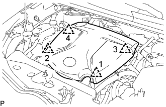
Поднимите крышку двигателя № 1, чтобы освободить 4 фиксатора в порядке, показанном на рисунке, и снимите крышку двигателя № 1.
Note:Попытка одновременно освободить задние и передние фиксаторы может привести к повреждению крышки двигателя № 1.
-
- Click here
DISCONNECT SENSOR INSULATOR
-
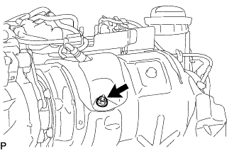
Remove the nut and disconnect the sensor insulator.
-
- Click here
DISCONNECT VACUUM CONTROL VALVE BRACKET
-
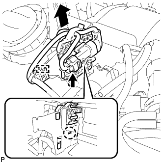
Disconnect the differential pressure sensor connector.
-
Detach the wire harness clamp.
-
Remove the claw as shown in the illustration, and then slide the bracket clamp with differential pressure sensor to disconnect the bracket clamp with differential pressure sensor from the vacuum control valve bracket.
-
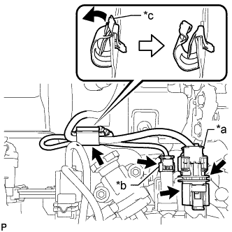
Disconnect the exhaust gas temperature sensor connector.
Table 1. Text in Illustration *a Air Fuel Ratio Sensor Connector *b Exhaust Gas Temperature Sensor Connector *c Clamp -
Disconnect the air fuel ratio sensor connector.
-
Raise the air fuel ratio sensor connector from the vacuum control valve bracket.
-
Move the clamp as shown in the illustration, and disconnect the air fuel ratio sensor and exhaust gas temperature sensor.
Note:Disconnect the sensors while opening the clamp.
-
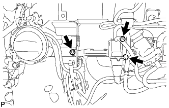
Using a T45 "TORX" socket wrench, remove the 3 screws and disconnect the vacuum control valve bracket.
-
- Click here
REMOVE EXHAUST GAS TEMPERATURE SENSOR (for Sensor 1)
Note:If the exhaust gas temperature sensor is dropped, replace it with a new one.
-
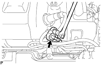
Using a 14 mm union nut wrench, remove the exhaust gas temperature sensor.
-