МОНОЛИТНЫЙ КАТАЛИТИЧЕСКИЙ НЕЙТРАЛИЗАТОР УСТАНОВКА
-
INSTALL NO. 2 MANIFOLD CONVERTER INSULATOR
-
Install the No. 2 manifold converter insulator with the 3 bolts.
- Torque:
- 29 N*m { 291 kgf*cm, 21 ft.*lbf }
-
-
INSTALL NO. 2 VACUUM PIPE
-
Temporarily install the No. 2 vacuum pipe with the union nut and bolt.
-
Tighten the bolt.
- Torque:
- 25 N*m { 255 kgf*cm, 18 ft.*lbf }
-
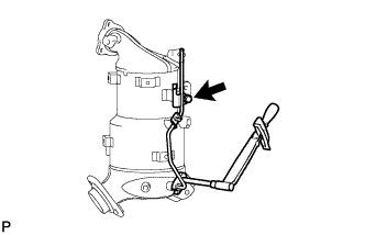
Using a 14 mm union nut wrench, tighten the union nut of the No. 2 vacuum pipe.
- Torque:
- 30 N*m { 306 kgf*cm, 22 ft.*lbf }
Note
Use the formula to calculate special torque values for situations where a union nut wrench is combined with a torque wrench Click here.
-
-
INSTALL NO. 1 VACUUM PIPE
-
Temporarily install the No. 1 vacuum pipe with the union nut and bolt.
-
Tighten the bolt.
- Torque:
- 25 N*m { 255 kgf*cm, 18 ft.*lbf }
-
Using a 17 mm union nut wrench, tighten the union nut of the No. 1 vacuum pipe.
- Torque:
- 48 N*m { 489 kgf*cm, 35 ft.*lbf }
Note
Use the formula to calculate special torque values for situations where a union nut wrench is combined with a torque wrench Click here.
-
-
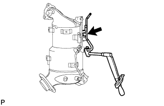
INSTALL EXHAUST GAS TEMPERATURE SENSOR (for Upper Side)
Note
If the sensor is dropped, replace it with a new one.
-
Using a 14 mm union nut wrench, install the sensor.
- Torque:
- 30 N*m { 306 kgf*cm, 22 ft.*lbf }
Note
Use the formula to calculate special torque values for situations where a union nut wrench is combined with a torque wrench Click here.
-
Attach the sensor connector clamp.
-
-
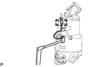
INSTALL EXHAUST GAS TEMPERATURE SENSOR (for Lower Side)
Note
If the sensor is dropped, replace it with a new one.
-
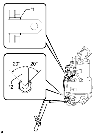
Text in Illustration *1 White Tube *2 Protective Tube Temporarily install the sensor with the union nut.
-
Attach the sensor connector clamp.
-
Temporarily install the clamp with the nut.
Note
Make sure the clamp is aligned with the white tube of the wire harness as shown in the illustration.
-
Tighten the nut.
- Torque:
- 6.4 N*m { 65 kgf*cm, 57 in.*lbf }
-
Using a 14 mm union nut wrench, tighten the union nut of the sensor.
- Torque:
- 30 N*m { 306 kgf*cm, 22 ft.*lbf }
Note
-
When tightening the union nut, make sure that the protective tube of the sensor is within the range shown in the illustration.
-
Use the formula to calculate special torque values for situations where a union nut wrench is combined with a torque wrench Click here.
-
-
INSTALL NO. 2 VACUUM TRANSMITTING HOSE ASSEMBLY
-
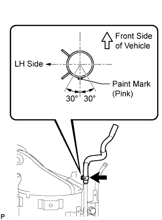
Install the No. 2 vacuum transmitting hose to the No. 2 vacuum pipe.
Tech Tips
The direction of the hose clamp is indicated in the illustration.
-
-
INSTALL VACUUM TRANSMITTING HOSE ASSEMBLY
-
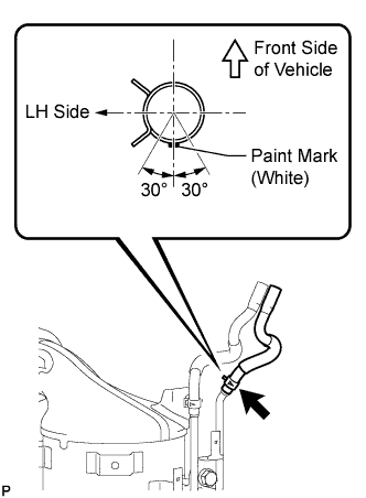
Install the vacuum transmitting hose to the No. 1 vacuum pipe.
Tech Tips
The direction of the hose clamp is indicated in the illustration.
-
-
INSTALL EXHAUST MANIFOLD CONVERTER SUB-ASSEMBLY
-
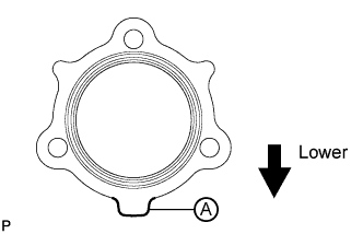
Install a new gasket to the turbocharger.
Tech Tips
Make sure that the part labeled A is facing downwards as shown in the illustration.
-
Temporarily install the exhaust manifold converter with 3 new nuts.
-
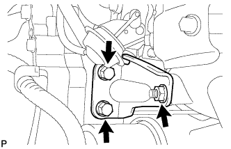
Temporarily install the No. 2 exhaust manifold stay with the 2 bolts and nut.
-
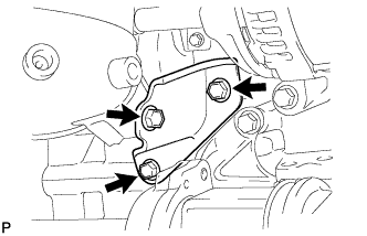
Temporarily install the No. 2 manifold stay with the 3 bolts.
-
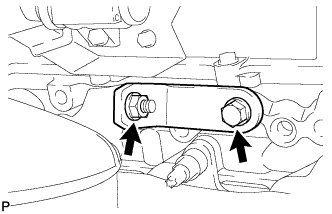
Temporarily install the manifold stay with the bolt and nut.
-
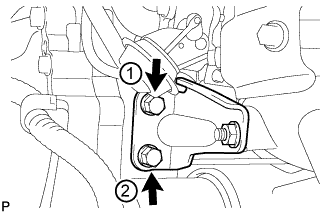
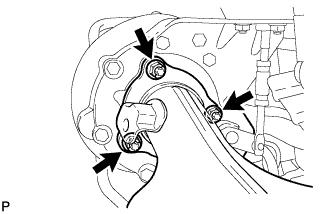
Tighten the 2 bolts of the No. 2 exhaust manifold stay in the order shown in the illustration.
- Torque:
- 56 N*m { 571 kgf*cm, 41 ft.*lbf }
-
Tighten the 3 nuts of the exhaust manifold converter.
- Torque:
- 25 N*m { 255 kgf*cm, 18 ft.*lbf }
Note
Tighten the nuts while pressing the exhaust manifold converter against the engine.
-
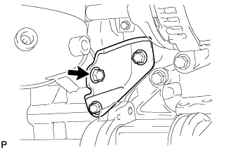
Tighten the nut of the No. 2 exhaust manifold stay.
- Torque:
- 56 N*m { 571 kgf*cm, 41 ft.*lbf }
-
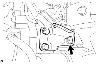
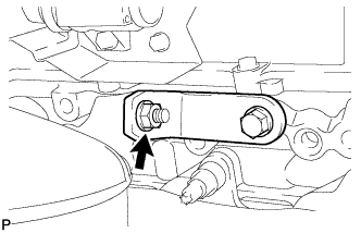
Tighten the bolt of the No. 2 manifold stay shown in the illustration.
- Torque:
- 56 N*m { 571 kgf*cm, 41 ft.*lbf }
Note
Tighten the bolt while pressing the No. 2 manifold stay against the exhaust manifold converter and cylinder block.
-
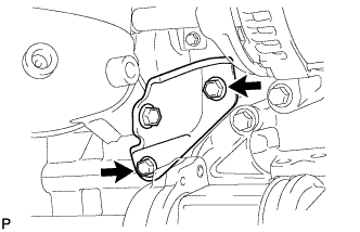
Tighten the 2 bolts of the No. 2 manifold stay shown in the illustration.
- Torque:
- 56 N*m { 571 kgf*cm, 41 ft.*lbf }
-
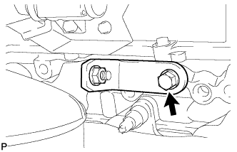
Tighten the bolt of the manifold stay.
- Torque:
- 25 N*m { 255 kgf*cm, 18 ft.*lbf }
Note
Tighten the bolt while pressing the manifold stay against the exhaust manifold converter and cylinder block.
-
Tighten the nut of the manifold stay.
- Torque:
- 25 N*m { 255 kgf*cm, 18 ft.*lbf }
-
Connect the 2 connectors.
-
-
INSTALL NO. 1 MANIFOLD CONVERTER INSULATOR
-
Install the No. 1 manifold converter insulator with the 5 bolts.
- Torque:
- 29 N*m { 291 kgf*cm, 21 ft.*lbf }
-
-
INSTALL ENGINE ASSEMBLY
-
PERFORM CATALYST RECORD OF DPNR THERMAL DETERIORATION CLEAR FUNCTION