ТОПЛИВНАЯ СИСТЕМА СХЕМА СИСТЕМЫ
-
FUEL FLOW DIAGRAM
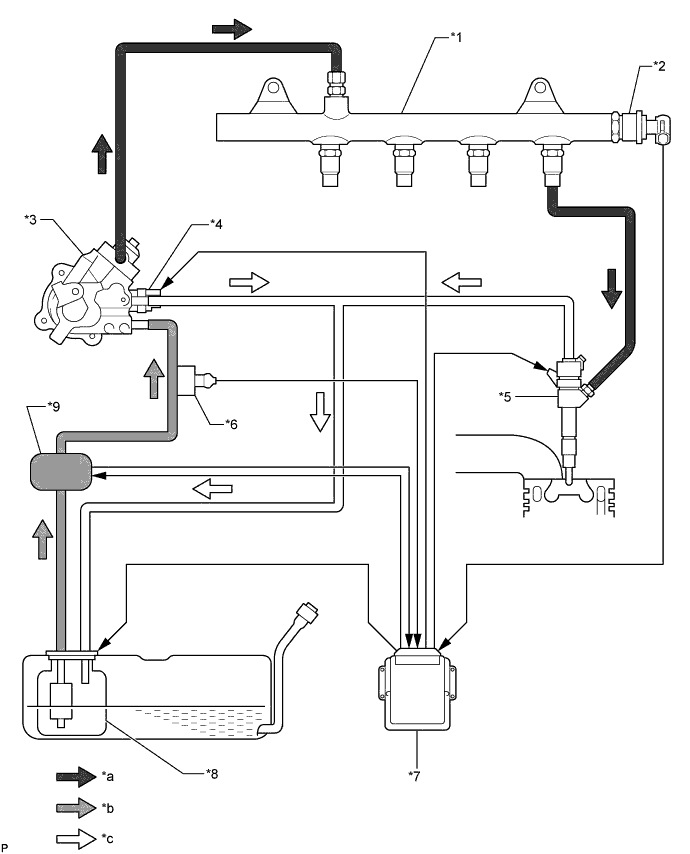
Text in Illustration *1 Common Rail Assembly *2 Fuel Pressure Sensor *3 Fuel Supply Pump Assembly *4 Fuel Quantity Control Valve *5 Injector Assembly *6 Fuel Temperature Sensor *7 ECM *8 Fuel Suction with Pump and Gauge Tube Assembly
- Fuel Pump
- Fuel Sender Gauge Assembly
*9 Fuel Filter Assembly
- Fuel Heater
- Fuel Level Warning Switch
- Pressure Sensor
- - *a High Pressure Fuel Line *b Low Pressure Fuel Line *c Return Fuel Line - - -
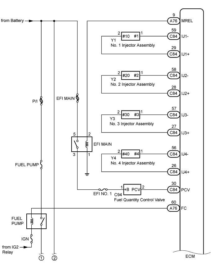
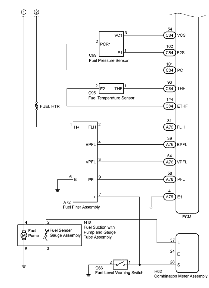
FUEL SYSTEM WIRING DIAGRAM