ТОПЛИВНЫЙ БАК УСТАНОВКА

-
УСТАНОВИТЕ ВОЗВРАТНУЮ ТРУБКУ ТОПЛИВНОГО БАКА
-
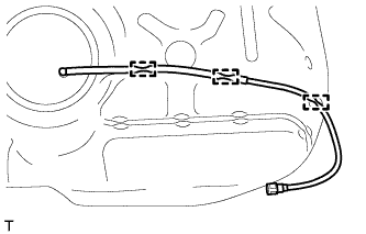
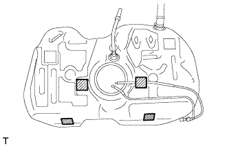
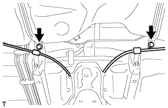
Присоедините возвратную трубку топливного бака к 3 зажимам, чтобы закрепить ее.
-
-
УСТАНОВИТЕ ПОДАЮЩИЙ ТОПЛИВОПРОВОД В СБОРЕ
-
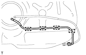
Присоедините подающий топливопровод к 4 зажимам, чтобы закрепить его.
-
-
УСТАНОВИТЕ ШЛАНГ, СОЕДИНЯЮЩИЙ ТОПЛИВНЫЙ БАК И НАЛИВНУЮ ТРУБУ
-
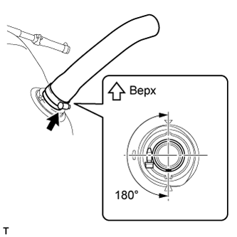
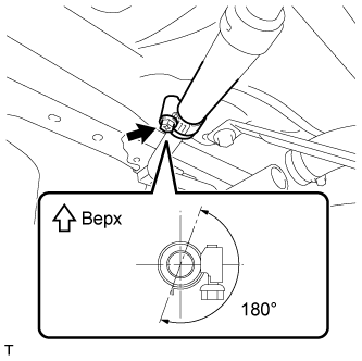
Присоедините шланг наливной трубы к топливному баку и затяните болт зажима шланга таким образом, чтобы зажим располагался, как показано на рисунке.
Note
Обязательно затяните хомут шланга под правильным углом.
Tech Tips
В положении, показанном на рисунке, хомут шланга также можно расположить так, чтобы болт хомута шланга находился на противоположной стороне шланга головкой вверх.
-
-
УСТАНОВИТЕ АМОРТИЗАТОР ТОПЛИВНОГО БАКА № 2
-
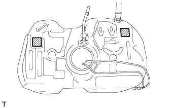
Установите 2 новых амортизатора топливного бака № 2 в места, показанные на рисунке.
-
-
УСТАНОВИТЕ АМОРТИЗАТОР № 1 ТОПЛИВНОГО БАКА
-
Установите 4 новых амортизатора топливного бака № 1 в места, показанные на рисунке.
-
-
УСТАНОВИТЕ ТОПЛИВНЫЙ БАК В СБОРЕ
-
Подоприте топливный бак телескопическим гидравлическим домкратом.
-
Поднимите телескопический гидравлический домкрат и установите топливный бак на автомобиль.
Note
-
Будьте осторожны, не уроните топливный бак.
-
Устанавливая топливный бак, слегка наклоните его, что он не задел рычаг подвески или другие расположенные рядом детали.
-
-
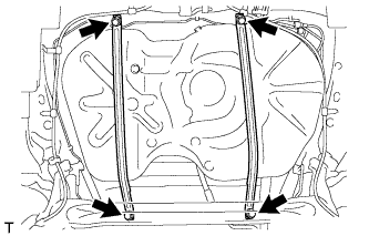
Установите 2 хомута крепления бака и зафиксируйте их 4 болтами.
- Torque:
- 39 Н*м { 398 кгс*см, 29 фунт-сила-футов }
-
Подсоедините подающий топливопровод.
-
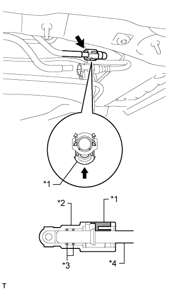
Обозначения на рисунке *1 Крепежная деталь *2 Соединитель топливопровода *3 Кольцевое уплотнение *4 Патрубок Чтобы соединить подающий топливопровод с трубкой, совместите разъем топливопровода с трубкой и нажмите на разъем топливопровода, чтобы он сел на место. Затем нажмите на фиксатор до защелкивания захватов.
Note
-
Перед выполнением данной операции убедитесь в отсутствии царапин и посторонних частиц вокруг соединяемых частей разъема топливопровода и топливопровода.
-
После подсоединения подающего топливопровода убедитесь в надежности соединения, попробовав разъединить трубный соединитель.
-
-
-
Подсоедините возвратную трубку топливного бака.
-
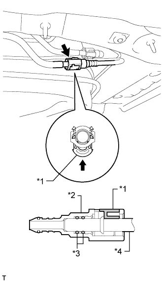
Обозначения на рисунке *1 Крепежная деталь *2 Соединитель топливопровода *3 Кольцевое уплотнение *4 Патрубок Чтобы соединить возвратную трубку топливного бака с трубой, совместите разъем трубки с трубой и нажмите на разъем, чтобы он сел на место. Затем нажмите на фиксатор до защелкивания захватов.
Note
-
Перед выполнением данной операции убедитесь в отсутствии царапин и посторонних частиц вокруг соединяемых частей разъема топливопровода и топливопровода.
-
После подсоединения возвратной трубки топливного бака убедитесь в надежности соединения, попробовав разъединить трубный соединитель.
-
-
-
Подсоедините трос привода стояночного тормоза и закрепите 2 болтами.
- Torque:
- 6,0 Н*м { 61 кгс*см, 53 фунт-сила-дюйма }
-
Подсоедините шланг сапуна к наливной трубе топливного бака и затяните болт зажима шланга таким образом, чтобы зажим располагался, как показано на рисунке.
Note
Обязательно затяните хомут шланга под правильным углом.
-
-
ПОДСОЕДИНИТЕ ШЛАНГ, СОЕДИНЯЮЩИЙ ТОПЛИВНЫЙ БАК И НАЛИВНУЮ ТРУБКУ
-
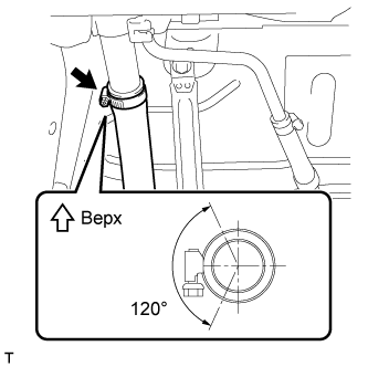
Подсоедините шланг наливной трубы к наливной трубе топливного бака и затяните болт зажима шланга таким образом, чтобы зажим располагался, как показано на рисунке.
Note
Обязательно затяните хомут шланга под правильным углом.
-
-
УСТАНОВИТЕ ЗАЩИТУ ТОПЛИВНОГО БАКА № 1
-
Установите подкладку защиты топливного бака.
-
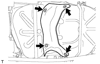
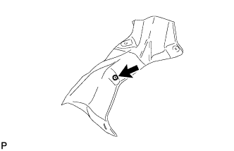
Установите защиту топливного бака № 1 и закрепите ее 4 фиксаторами.
-
-
УСТАНОВИТЕ СКОБУ БОКОВОГО ЗАЩИТНОГО БРУСА ЗАДНЕГО ПОЛА В СБОРЕ
-
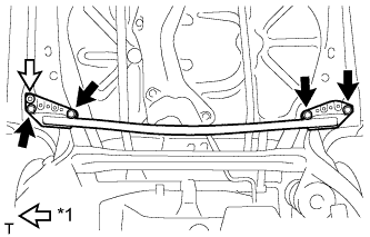
Обозначения на рисунке *1 Фиксатор Присоедините фиксатор и закрепите скобу бокового защитного бруса заднего пола 4 болтами.
- Torque:
- 54 Н*м { 551 кгс*см, 40 фунт-сила-футов }
-
-
УСТАНОВИТЕ НАКЛАДКУ ЛЕВОГО БОКОВОГО БРУСА ЗАДНЕГО ПОЛА
-
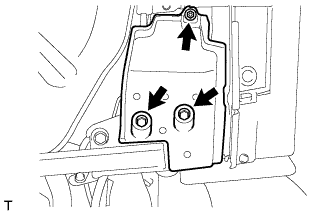
Установите накладку бокового защитного бруса заднего пола и закрепите ее гайкой и 2 болтами.
-
-
УСТАНОВИТЕ НАКЛАДКУ ПРАВОГО БОКОВОГО БРУСА ЗАДНЕГО ПОЛА
-
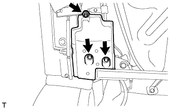
Установите накладку бокового защитного бруса заднего пола и закрепите ее гайкой и 2 болтами.
-
-
УСТАНОВИТЕ ЛЕВУЮ ЦЕНТРАЛЬНУЮ ПАНЕЛЬ ПЕРЕДНЕГО ПОЛА
-
Обозначения на рисунке *1 Уплотнительная шайба Присоедините уплотнительную втулку и закрепите центральную панель переднего пола гайкой.
-
-
УСТАНОВИТЕ ПРАВУЮ ЦЕНТРАЛЬНУЮ ПАНЕЛЬ ПЕРЕДНЕГО ПОЛА
-
Обозначения на рисунке *1 Уплотнительная шайба Присоедините уплотнительную втулку и закрепите центральную панель переднего пола гайкой.
-
-
ДОБАВЬТЕ ТОПЛИВО
-
УСТАНОВИТЕ ПРОДУВОЧНЫЙ ПАТРУБОК ТОПЛИВНОГО БАКА В СБОРЕ
-
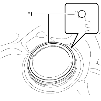
Text in Illustration *1 New Gasket Apply a light coat of diesel fuel to a new gasket and install the gasket to the fuel tank.
-
Install the fuel tank vent tube to the fuel tank.
Note
Make sure that the fuel sender gauge arm does not bend.
-
Text in Illustration *1 Notch *2 Protrusion Align the protrusions of the fuel tank vent tube with the notches of the fuel tank.
-
-
УСТАНОВИТЕ КРЕПЕЖНУЮ ДЕТАЛЬ ДАТЧИКА ТОПЛИВНОГО НАСОСА
-
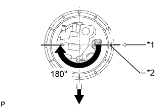
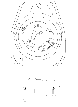
Text in Illustration *1 Start Mark
(Fuel Tank Side)
*2 Start Mark
(Fuel Pump Gauge Retainer Side)

Front Side of Vehicle While holding the fuel suction with pump and gauge tube by hand to prevent it from tilting, align the start marks on a new fuel pump gauge retainer and fuel tank and tighten the fuel pump gauge retainer 180° by hand.
Tech Tips
Check that there is no damage, dents, foreign matter, or other defects on the threads of the fuel tank.
-
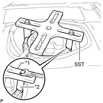
Text in Illustration *1 SST (Plate) *2 SST (Claw) Temporarily install SST (plate and 2 claws) to the fuel pump gauge retainer.
- SST
- 09808-14030
Tech Tips
-
Be sure to use 2 SST (claws) as shown in the illustration.
-
Engage SST (claws) securely with the fuel pump gauge retainer ribs to secure SST.
-
While securely pressing SST (claws) against the fuel pump gauge retainer ribs, install the 2 bolts.
Tech Tips
Install SST while pressing SST (claws) against the fuel pump gauge retainer (towards the center of SST).
-
Install SST (handle).
-
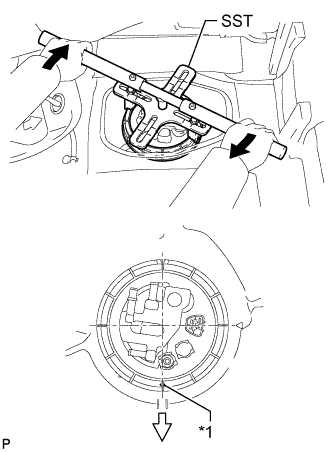
Text in Illustration *1 Start Mark
(Fuel Pump Gauge Retainer Side)
Turn 
Front Side of Vehicle Tighten the fuel pump gauge retainer approximately 270° so that the start mark on the fuel pump gauge retainer is in the position shown in the illustration.
- SST
- 09808-14030
Note
-
Do not use any tools other than those specified in this operation. Damage to the fuel pump gauge retainer or fuel tank may result.
-
Do not press down on SST excessively as this may make the fuel pump gauge retainer hard to rotate, and may damage components.
-
Make sure to rotate SST (handle) horizontally. If SST (handle) is rotated at an angle, SST may come off.
-
Do not spin SST too fast or use an impact wrench as this may result in damage to components.
-
If SST comes off of the fuel pump gauge retainer, loosen SST (bolts) and reinstall SST.
Tech Tips
-
Lightly press down on SST to prevent it from separating from the fuel pump gauge retainer. While pressing SST, rotate the handle slowly to tighten the fuel pump gauge retainer.
-
The tips of SST (claws) can be fitted onto the ribs of the fuel pump gauge retainer.
-
-
ПОДСОЕДИНИТЕ ВОЗВРАТНУЮ ТРУБКУ ТОПЛИВНОГО БАКА
-
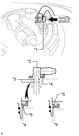
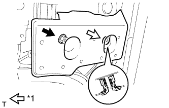
Text in Illustration *1 Tube Joint Clip *2 Fuel Tube Joint *3 O-Ring *4 Tube Joint Clip *5 Collar *a CORRECT *b INCORRECT Push the fuel tube joint into the plug of the fuel tank vent tube, and then install the tube joint clip.
Note
-
Check that there are no scratches or foreign objects on the connecting parts.
-
Check that the fuel tube joint is inserted securely.
-
Check that the tube joint clip is on the collar of the fuel tube joint.
-
After installing the tube joint clip, check that the fuel tube joint cannot be pulled off.
-
-
-
ПОДСОЕДИНИТЕ ПОДАЮЩИЙ ТОПЛИВОПРОВОД В СБОРЕ
-
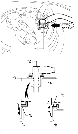
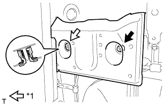
Text in Illustration *1 Tube Joint Clip *2 Fuel Tube Joint *3 O-Ring *4 Tube Joint Clip *5 Collar *a CORRECT *b INCORRECT Push the fuel tube joint into the plug of the fuel tank vent tube, and then install the tube joint clip.
Note
-
Check that there are no scratches or foreign objects on the connecting parts.
-
Check that the fuel tube joint is inserted securely.
-
Check that the tube joint clip is on the collar of the fuel tube joint.
-
After installing the tube joint clip, check that the fuel tube joint cannot be pulled off.
-
-
-
УСТАНОВИТЕ КРЫШКУ ТЕХНОЛОГИЧЕСКОГО ОТВЕРСТИЯ ЗАДНЕГО ПОЛА
-
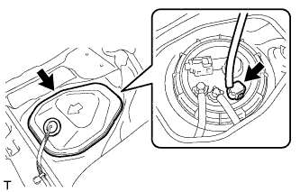
Connect the sender gauge connector.
-
Install the rear floor service hole cover with new butyl tape.
Note
Be careful that the rear floor service hole cover does not overlap the protrusions of the floor panel when installing.
-
-
УДАЛИТЕ ВОЗДУХ ИЗ ТОПЛИВНОЙ СИСТЕМЫ
-
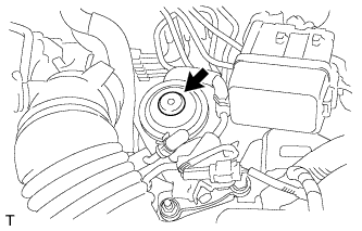
Using the hand pump mounted on the fuel filter cap, bleed the air from the fuel system. Continue pumping until the pump resistance increases.
Note
-
Hand pump pumping speed: Max. 2 strokes/ sec.
-
The hand pump must be pushed with a full stroke during pumping.
-
When the fuel pressure at the supply pump inlet port reaches a saturated pressure, the hand pump resistance increases.
-
If pumping is interrupted during the air bleeding process, fuel in the fuel line may return to the fuel tank. Continue pumping until the hand pump resistance increases.
-
If the hand pump resistance does not increase despite consecutively pumping 200 times or more, there may be a fuel leak between the fuel tank and fuel filter, the hand pump may be malfunctioning, or the vehicle may have run out of fuel.
-
If air bleeding using the hand pump is incomplete, the common rail pressure does not rise to the pressure range necessary for normal use, and the engine cannot be started.
-
-
Start the engine.
Note
-
Even if air bleeding using the hand pump has been completed, the starter may need to be cranked for 10 seconds or more to start the engine.
-
Do not crank the engine continuously for more than 20 seconds. The battery may be discharged.
-
Use a fully-charged battery.
-
When the engine can be started, proceed to the next step.
-
If the engine cannot be started, bleed the air again using the hand pump until the hand pump resistance increases (refer to the procedures above). Then start the engine.
-
-
Turn the ignition switch off.
-
Connect the intelligent tester to the DLC3.
-
Turn the ignition switch to ON and turn the intelligent tester on.
-
Clear the DTCs Click here.
-
Start the engine.*1
-
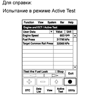
Enter the following menus: Powertrain / Engine and ECT / Active Test / Test the Fuel Leak.*2
-
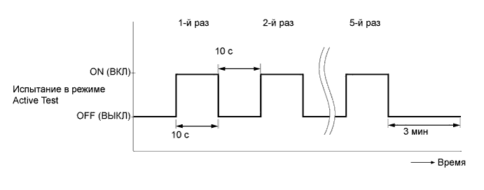
Perform the following test 5 times with on/off intervals of 10 seconds: Active Test / Test the Fuel Leak.*3
-
Allow the engine to idle for 3 minutes or more after performing the Active Test for the fifth time.
Tech Tips
When the Active Test "Test the Fuel Leak" is used to change the pump control mode, the actual fuel pressure inside the common rail drops below the target fuel pressure when the Active Test is off, but this is normal and does not indicate a pump malfunction.
-
Enter the following menus: Powertrain / Engine and ECT / DTC.
-
Read Current DTCs.
-
When no DTCs are output, the air bleeding is completed.
-
If any DTCs are output, proceed to the next step.
-
-
Clear the DTCs Click here.
-
Repeat steps *1 to *3.
-
Enter the following menus: Powertrain / Engine and ECT / DTC.
-
Read Current DTCs.
OK No DTCs are output.
-
-
ПРОВЕРЬТЕ, НЕТ ЛИ УТЕЧЕК ТОПЛИВА
Tech Tips
Using the intelligent tester to perform Active Tests allow relays, VSVs, actuators and other items to be operated without removing any parts. This non-intrusive functional inspection can be very useful because intermittent operation may be discovered before parts or wiring is disturbed. Performing Active Tests early in troubleshooting is one way to save diagnostic time. Data List information can be displayed while performing Active Tests.
-
Perform Active Test.
-
Connect the intelligent tester to the DLC3.
-
Turn the ignition switch to ON.
-
Start the engine.
-
Turn the intelligent tester on.
-
Enter the following menus: Powertrain / Engine / Active Test.
-
Perform the Active Test.
Tester Display Test Part Control Range Diagnostic Notes Test the Fuel Leak Pressurizes common rail internal fuel pressure, and checks for fuel leaks Stop/Start Performs inspection of the high pressure fuel system.
-
Engine Speed: 2050 rpm
-
Fuel Pressure: 172000 kPa
-
Target Common Rail Pressure: 176000 kPa
-
Target Pump SCV Current: 1.4 A
-
MAP: 176 kPa
-
MAF: 39 g/sec.
-
-
-
-
УСТАНОВИТЕ ЗАДНЕЕ ЦЕНТРАЛЬНОЕ СИДЕНЬЕ В СБОРЕ (для моделей с задним сиденьем № 1)
-
Установите центральное заднее сиденье в сборе (см. стр. Click here).
-
-
УСТАНОВИТЕ ЗАДНЕЕ СИДЕНЬЕ № 1 В СБОРЕ (для моделей с задним сиденьем № 1)
-
Установите заднее сиденье № 1 в сборе (см. стр. Click here).
-
-
УСТАНОВИТЕ ВЫПУСКНУЮ ТРУБУ В СБОРЕ
-
Установите выпускную трубу в сборе (см. стр. Click here).
-
-
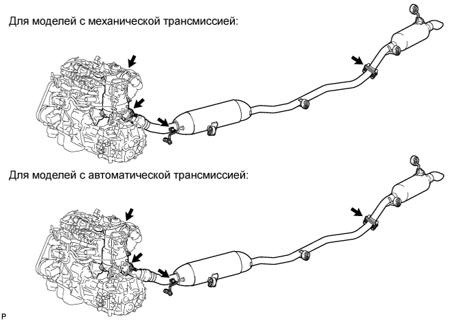
ПРОВЕРЬТЕ, НЕТ ЛИ УТЕЧЕК ОТРАБОТАВШИХ ГАЗОВ
-
Убедитесь в отсутствии утечек отработавших газов в местах (зонах соединений выпускных труб и зонах установки всех датчиков), показанных на рисунке.
-