ТОПЛИВНЫЙ ФИЛЬТР ЗАМЕНА

-
REMOVE NO. 1 ENGINE COVER
-
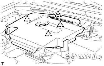
Возьмитесь сзади за крышку и медленно поднимите ее, чтобы разъединить задний фиксатор крышки. Продолжайте поднимать крышку так, чтобы освободить 3 передних и боковых фиксатора крышки, после чего снимите крышку.
Note
Попытка освободить задний и передние фиксаторы за один прием может привести к поломке крышки.
-
-
REMOVE AIR CLEANER CAP SUB-ASSEMBLY
-
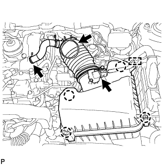
Открепите зажим и отсоедините разъем датчика массового расхода воздуха.
-
Отсоедините шланг системы принудительной вентиляции картера.
-
Отсоедините шланг воздушного фильтра.
-
Освободите 4 зажима и снимите крышку воздушного фильтра.
-
-
REMOVE AIR CLEANER FILTER ELEMENT SUB-ASSEMBLY
-
REMOVE AIR CLEANER CASE SUB-ASSEMBLY
-
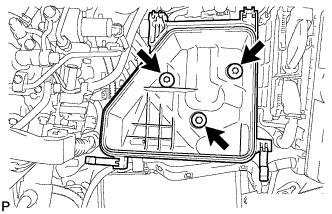
Выверните 3 болта и снимите корпус воздушного фильтра.
-
-
REMOVE FUEL FILTER ASSEMBLY (w/o Combustion Type Power Heater)
-
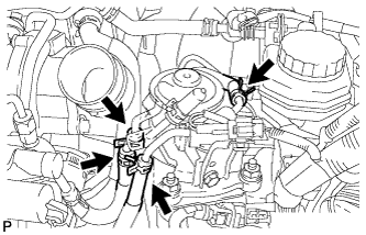
Disconnect the 4 fuel hoses.
-
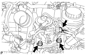
Disconnect the level warning switch connector.
-
Remove the 2 nuts and fuel filter assembly.
-
-
REMOVE FUEL FILTER ASSEMBLY (w/ Combustion Type Power Heater)
-
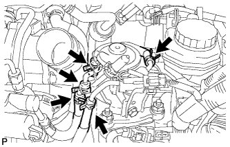
Disconnect the 5 fuel hoses.
-
Disconnect the level warning switch connector.
-
Remove the 2 nuts and fuel filter assembly.
-
-
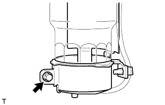
DRAIN FUEL
-
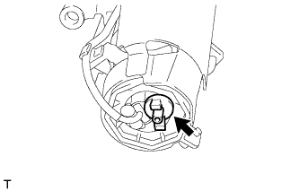
Loosen the drain bolt and drain the fuel from the fuel filter.
-
-
REMOVE FUEL FILTER GASKET
-
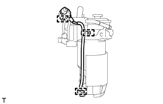
Detach the 3 harness clamps.
-
Remove the bolt, filter cover and filter gasket.
-
-
REMOVE LEVEL WARNING SWITCH
-
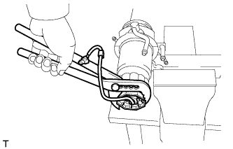
Clamp the fuel filter assembly in a vise between aluminum plates.
Note
Be careful not to damage the fuel filter cap.
-
Using pliers, remove the level warning switch.
Note
Be careful not to damage the level warning switch.
-
Remove the gasket from the level warning switch.
-
-
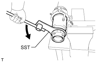
REMOVE FUEL FILTER ELEMENT SUB-ASSEMBLY
-
Using SST, remove the fuel filter element.
- SST
- 09228-64010
-
-
INSTALL FUEL FILTER ELEMENT SUB-ASSEMBLY
-
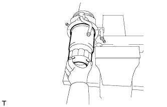
Check and clean the installation surface of the fuel filter.
-
Apply fuel to the gasket of a new fuel filter element.
-
Lightly screw the fuel filter element into place, and tighten it until the gasket comes into contact with the seat.
-
Tighten the fuel filter element an additional 3/4 turn by hand.
-
-
INSTALL LEVEL WARNING SWITCH
-
Install a new gasket to the level warning switch.
-
Apply fuel to the gasket of the level warning switch.
-
Install the level warning switch to the fuel filter and tighten it by hand.
-
-
INSTALL FUEL FILTER GASKET
-
Install the filter gasket and filter cover to the fuel filter assembly.
-
Tighten the bolt.
- Torque:
- 3.4 N*m { 35 kgf*cm, 30 in.*lbf }
-
Attach the 3 harness clamps.
-
-
INSTALL FUEL FILTER ASSEMBLY (w/ Combustion Type Power Heater)
-
Install the fuel filter assembly with the 2 nuts.
- Torque:
- 18 N*m { 178 kgf*cm, 13 ft.*lbf }
-
Connect the level warning switch connector.
-
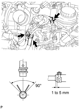
Connect the No. 1 fuel hose, No. 2 fuel hose and No. 3 fuel hose.
Tech Tips
-
Align the alignment marks and connect the hose.
-
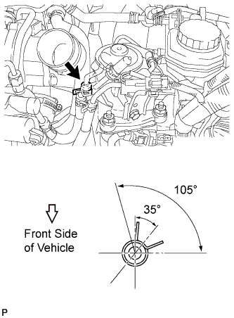
Align the claws of the clamp with the hose alignment mark as shown in the illustration.
-
Position the clamp so that the distance from the end of the hose is 1 to 5 mm (0.0394 to 0.197 in.).
-
-
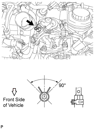
Connect the No. 4 fuel hose.
Tech Tips
Make sure the direction of the hose clamp is as shown in the illustration.
-
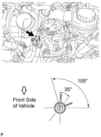
Connect the heater fuel hose.
Tech Tips
-
Align the alignment marks and connect the hose.
-
Make sure the direction of the hose clamp is as shown in the illustration.
-
-
-
INSTALL FUEL FILTER ASSEMBLY (w/o Combustion Type Power Heater)
-
Install the fuel filter assembly with the 2 nuts.
- Torque:
- 18 N*m { 178 kgf*cm, 13 ft.*lbf }
-
Connect the level warning switch connector.
-
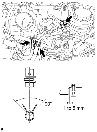
Connect the No. 1 fuel hose, No. 2 fuel hose and No. 3 fuel hose.
Tech Tips
-
Align the alignment marks and connect the hose.
-
Align the claws of the clamp with the hose alignment mark as shown in the illustration.
-
Position the clamp so that the distance from the end of the hose is 1 to 5 mm (0.0394 to 0.197 in.).
-
-
Connect the No. 4 fuel hose.
Tech Tips
Make sure the direction of the hose clamp is as shown in the illustration.
-
-
INSTALL AIR CLEANER CASE SUB-ASSEMBLY
-
Установите корпус воздушного фильтра и закрепите его 3 болтами.
- Torque:
- 7,0 Н*м { 71 кгс*см, 62 фунт-сила-дюйма }
-
-
INSTALL AIR CLEANER FILTER ELEMENT SUB-ASSEMBLY
-
INSTALL AIR CLEANER CAP SUB-ASSEMBLY
-
Подсоедините шланг воздушного фильтра.
-
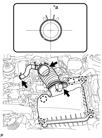
Обозначения на рисунке *a Верх Присоедините 4 зажима, чтобы закрепить крышку воздушного фильтра.
-
Подсоедините шланг системы принудительной вентиляции картера.
-
Подсоедините разъем датчика массового расхода воздуха и закрепите зажимом.
-
-
BLEED AIR FROM FUEL SYSTEM
-
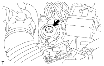
Using the hand pump mounted on the fuel filter cap, bleed the air from the fuel system. Continue pumping until the pump resistance increases.
Note
-
Hand pump pumping speed: Max. 2 strokes/ sec.
-
The hand pump must be pushed with a full stroke during pumping.
-
When the fuel pressure at the supply pump inlet port reaches a saturated pressure, the hand pump resistance increases.
-
If pumping is interrupted during the air bleeding process, fuel in the fuel line may return to the fuel tank. Continue pumping until the hand pump resistance increases.
-
If the hand pump resistance does not increase despite consecutively pumping 200 times or more, there may be a fuel leak between the fuel tank and fuel filter, the hand pump may be malfunctioning, or the vehicle may have run out of fuel.
-
If air bleeding using the hand pump is incomplete, the common rail pressure does not rise to the pressure range necessary for normal use, and the engine cannot be started.
-
-
Start the engine.
Note
-
Even if air bleeding using the hand pump has been completed, the starter may need to be cranked for 10 seconds or more to start the engine.
-
Do not crank the engine continuously for more than 20 seconds. The battery may be discharged.
-
Use a fully-charged battery.
-
When the engine can be started, proceed to the next step.
-
If the engine cannot be started, bleed the air again using the hand pump until the hand pump resistance increases (refer to the procedures above). Then start the engine.
-
-
Turn the ignition switch off.
-
Connect the intelligent tester to the DLC3.
-
Turn the ignition switch to ON and turn the intelligent tester on.
-
Clear the DTCs.
-
for DPF: Click here
-
for CCo: Click here
-
-
Start the engine.*1
-
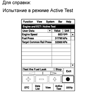
Enter the following menus: Powertrain / Engine and ECT / Active Test / Test the Fuel Leak.*2
-
Perform the following test 5 times with on/off intervals of 10 seconds: Active Test / Test the Fuel Leak.*3
-
Allow the engine to idle for 3 minutes or more after performing the Active Test for the fifth time.
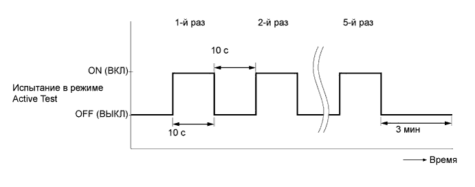
Tech Tips
When the Active Test "Test the Fuel Leak" is used to change the pump control mode, the actual fuel pressure inside the common rail drops below the target fuel pressure when the Active Test is off, but this is normal and does not indicate a pump malfunction.
-
Enter the following menus: Powertrain / Engine and ECT / DTC.
-
Read Current DTCs.
-
When no DTCs are output, the air bleeding is completed.
-
If any DTCs are output, proceed to the next step.
-
-
Clear the DTCs.
-
for DPF: Click here
-
for CCo: Click here
-
-
Repeat steps *1 to *3.
-
Enter the following menus: Powertrain / Engine and ECT / DTC.
-
Read Current DTCs.
OK No DTCs are output.
-
-
INSPECT FOR FUEL LEAK
Tech Tips
Using the intelligent tester to perform Active Tests allow relays, VSVs, actuators and other items to be operated without removing any parts. This non-intrusive functional inspection can be very useful because intermittent operation may be discovered before parts or wiring is disturbed. Performing Active Tests early in troubleshooting is one way to save diagnostic time. Data List information can be displayed while performing Active Tests.
-
Perform Active Test.
-
Connect the intelligent tester to the DLC3.
-
Turn the ignition switch to ON.
-
Start the engine.
-
Turn the intelligent tester on.
-
Enter the following menus: Powertrain / Engine / Active Test.
-
Perform the Active Test.
Tester Display Test Part Control Range Diagnostic Notes Test the Fuel Leak Pressurizes common rail internal fuel pressure, and checks for fuel leaks Stop/Start Performs inspection of the high pressure fuel system.
-
Engine Speed: 2050 rpm
-
Fuel Pressure: 172000 kPa
-
Target Common Rail Pressure: 176000 kPa
-
Target Pump SCV Current: 1400 mA
-
MAP: 176 kPa
-
MAF: 39 g/sec.
-
-
-
-
INSTALL NO. 1 ENGINE COVER
-
Введите в зацепление 4 фиксатора, чтобы закрепить крышку двигателя № 1.
-