БЛОК ДВИГАТЕЛЯ УСТАНОВКА
Note
-
Always be sure to check the tightening torque.
-
If the pressure lines are leaking after installation, they must be replaced.
-
Do not overtighten the pressure lines.
-
All pressure lines may only be reused 3 times. After the 3rd time, they must be replaced.
-
INSTALL DRIVE SHAFT BEARING BRACKET
-
Using a T50 "TORX" socket wrench, install the drive shaft bearing bracket with the 3 bolts.
- Torque:
- 64 N*m { 650 kgf*cm, 47 ft.*lbf }
-
-
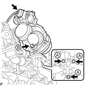
INSTALL VACUUM CONTROL VALVE BRACKET
-
Using a T20 "TORX" socket wrench, connect the vacuum control valve bracket with the 3 screws.
-
Attach the air fuel ratio sensor clamp to the vacuum control valve bracket.
-
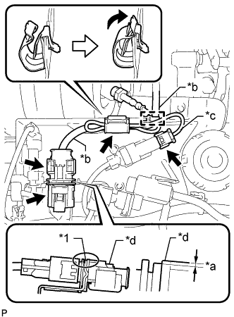
Text in Illustration *1 Vacuum Control Valve Bracket *a 1.5 mm (0.0591 in.) or less *b Air Fuel Ratio Sensor Connector Wire *c Exhaust Gas Temperature Sensor Connector Wire *d Air Fuel Ratio Sensor Connector Move the clamp as shown in the illustration, and secure the air fuel ratio sensor and exhaust gas temperature sensor with the clamp.
Note
The wire harness may become damaged if not installed when the clamp is open.
-
Lower the air fuel ratio sensor connector to the position shown in the illustration.
-
Connect the air fuel ratio sensor connector.
-
Connect the exhaust gas temperature sensor connector.
-
Attach the wire harness clamp.
-
Connect the exhaust gas temperature sensor connector.
-
-
INSTALL EGR BYPASS VALVE SWITCHING VALVE ASSEMBLY
-
Attach the claw and install the EGR bypass valve switching valve assembly.
-
Connect the 2 vacuum hoses.
-
Connect the EGR bypass valve switching valve assembly connector.
-
Push on the EGR bypass valve switching valve assembly connector until the spring lock makes a sound and returns to its original position.
Tech Tips
It is not necessary to push the spring lock down when connecting the EGR bypass valve switching valve assembly connector.
-
-
-
INSTALL GLOW PLUG ASSEMBLY
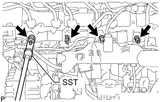
-
Using SST, install the 4 glow plug assemblies.
SST PZ4TB-04910-68 - Torque:
- 18 N*m { 178 kgf*cm, 13 ft.*lbf }
-
Connect the 4 connectors to the glow plug assemblies.
-
-
INSTALL COMMON RAIL ASSEMBLY
-
Install the common rail assembly to the cylinder head cover sub-assembly.
-
Using an E10 "TORX" socket wrench, install the 2 common rail assembly brackets with the 4 bolts.
Tech Tips
Refer to "SPECIFICATIONS - STANDARD BOLT" for the tightening torque.
-
Connect the fuel return tube.
-
Connect the pressure discharge valve connector.
-
Connect the fuel pressure sensor connector.
-
-
INSTALL INJECTION PIPE SUB-ASSEMBLY
Note
-
If the pressure lines are leaking after installation, they must be replaced.
-
Do not overtighten the pressure lines.
-
Temporarily install the 2 No. 1 injection pipe sub-assemblies and 2 No. 2 injection pipe sub-assemblies at the common rail assembly end by hand.
-
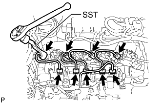
Using a SST, tighten the 4 union nuts at the common rail assembly end of the 2 No. 1 injection pipe sub-assemblies and 2 No. 2 injection pipe sub-assemblies as shown in the illustration.
SST PZ4TB-04959-10 - Torque:
- 24 N*m { 245 kgf*cm, 18 ft.*lbf }
Note
Reset SST in a timely manner to prevent bending of pressure lines.
-
Using SST, tighten the 4 union nuts at the 4 injector assembly ends of the 2 No. 1 injection pipe sub-assemblies and 2 No. 2 injection pipe sub-assemblies.
SST PZ4TB-04959-10 - Torque:
- 24 N*m { 245 kgf*cm, 18 ft.*lbf }
Note
Reset SST in a timely manner to prevent bending of pressure lines.
-
Check all components of the common rail system for tightness.
-
-
INSTALL NO. 3 INJECTION PIPE SUB-ASSEMBLY
Note
-
If the pressure lines are leaking after installation, they must be replaced.
-
Do not overtighten the pressure lines.
-
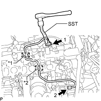
Text in Illustration *1 Rubber Grommet *2 Rubber Mount Install the fuel inlet pipe sub-assembly to the rubber grommet and rubber mount as shown in the illustration.
Note
Install the rubber mount and rubber grommet at the correct positions on the pressure line.
-
Temporarily install the union nut at the fuel supply pump assembly end and common rail assembly end of the fuel inlet pipe sub-assembly by hand.
-
Using SST, tighten the union nut at the fuel supply pump assembly end and common rail assembly end of the fuel inlet pipe sub-assembly as shown in the illustration.
SST PZ4TB-04959-10 - Torque:
- 24 N*m { 245 kgf*cm, 18 ft.*lbf }
Note
Reset SST in a timely manner to prevent bending of pressure lines.
-
-
INSTALL NO. 1 ENGINE HANGER
-
Install the No. 1 engine hanger to the cylinder head sub-assembly with the bolt.
Tech Tips
Refer to "SPECIFICATIONS - STANDARD BOLT" for the tightening torque.
-
-
INSTALL NO. 2 ENGINE HANGER
-
Install the No. 2 engine hanger to the cylinder head sub-assembly with the 2 bolts.
Tech Tips
Refer to "SPECIFICATIONS - STANDARD BOLT" for the tightening torque.
-
-
INSTALL EGR VALVE BRACKET
-
Install the EGR valve bracket to the cylinder head sub-assembly with the 2 bolts.
Tech Tips
Refer to "SPECIFICATIONS - STANDARD BOLT" for the tightening torque.
-
-
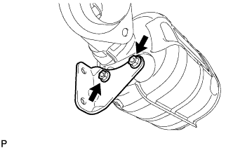
INSTALL TURBOCHARGER STAY
-
Install the turbocharger stay with the 2 bolts.
Tech Tips
Refer to "SPECIFICATIONS - STANDARD BOLT" for the tightening torque.
-
-
INSTALL NO. 2 TURBO INSULATOR
-
Install the No. 2 turbo insulator with the 3 bolts.
Tech Tips
Refer to "SPECIFICATIONS - STANDARD BOLT" for the tightening torque.
-
-
INSTALL NO. 1 TURBO OIL PIPE
-
Install the No. 1 turbo oil pipe, 2 nuts and 2 new gaskets with the union bolt.
- Torque:
- for union bolt
- 35 N*m { 357 kgf*cm, 26 ft.*lbf }
Tech Tips
Refer to "SPECIFICATIONS - STANDARD BOLT" for the tightening torque.
-
-
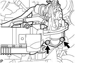
INSTALL EXHAUST MANIFOLD
-
Install 2 new gaskets to the cylinder head sub-assembly.
-
Temporarily install the exhaust manifold with the 8 nuts.
-
Step 1:
Tighten the 8 nuts of the exhaust manifold.
- Torque:
- 11 N*m { 112 kgf*cm, 8 ft.*lbf }
-
Step 2:
Tighten the 8 nuts again.
- Torque:
- 13 N*m { 133 kgf*cm, 10 ft.*lbf }
-
-
INSTALL EGR COOLER ASSEMBLY WITH EGR VALVE ASSEMBLY
-
Install a new water pipe to the EGR cooler assembly.
-
Install a new gasket to the No. 2 EGR pipe sub-assembly.
Tech Tips
Make sure that the claw of the gasket faces the No. 2 EGR pipe sub-assembly.
-
Temporarily install the EGR cooler assembly with EGR valve assembly with the 7 bolts.
-
Using a T45 "TORX" socket wrench, tighten the 2 bolts.
- Torque:
- 5.0 N*m { 51 kgf*cm, 44 in.*lbf }
-
Loosen the 2 bolts 90°.
-
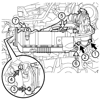
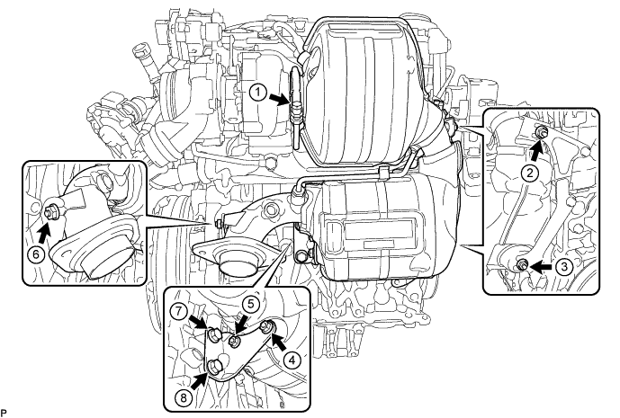
Tighten the 7 bolts labeled A, B and C, and then 2 nuts in the order shown in the illustration.
- Torque:
- for bolt A
- 13 N*m { 133 kgf*cm, 10 ft.*lbf }
- for bolt B
- 19 N*m { 194 kgf*cm, 14 ft.*lbf }
- for bolt C
- 8.0 N*m { 82 kgf*cm, 71 in.*lbf }
Text in Illustration 
Bolt A 
Bolt B 
Bolt C Tech Tips
-
When tightening the bolts labeled A, use a T45 "TORX" socket wrench.
-
When tightening the bolts labeled B, use a 6 mm hexagon wrench.
-
Connect the vacuum hoses to the EGR cooler assembly.
-
Connect the hose clamp to the EGR cooler hose.
-
Attach the clamp and connect the engine wire to the EGR valve assembly.
-
Connect the EGR valve assembly connector.
-
-
INSTALL TURBOCHARGER SUB-ASSEMBLY
-
Temporarily install a new gasket, the turbocharger sub-assembly and the 3 bolts labeled A.
-
Temporarily install the bolt labeled B.
-
Tighten the 4 bolts.
- Torque:
- for bolt A
- 25 N*m { 255 kgf*cm, 18 ft.*lbf }
- for bolt B
- 10 N*m { 102 kgf*cm, 7 ft.*lbf }
-
Connect the connector to the turbocharger sub-assembly.
-
-
CONNECT NO. 1 TURBO OIL PIPE
-
Connect the No. 1 turbo oil pipe and 2 new gaskets with the union bolt.
- Torque:
- 22 N*m { 224 kgf*cm, 16 ft.*lbf }
-
-
INSTALL TURBO OIL OUTLET PIPE
-
Install a new O-ring to the turbo oil outlet pipe.
-
Install a new gasket and the turbo oil outlet pipe with the 3 bolts.
- Torque:
- 10 N*m { 102 kgf*cm, 7 ft.*lbf }
-
-
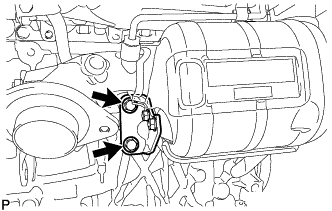
INSTALL EXHAUST MANIFOLD CONVERTER SUB-ASSEMBLY
Tech Tips
Perform "Inspection After Repair" after replacing the exhaust manifold converter sub-assembly Click here.
-
Temporarily install the manifold stay with the 2 nuts.
-
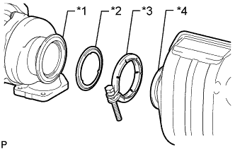
Text in Illustration *1 Turbocharger Sub-assembly *2 Gasket *3 V-band Clamp *4 Exhaust Manifold Converter Sub-assembly Temporarily install the exhaust manifold converter sub-assembly and engine bracket with the 3 nuts, 3 bolts, new V-band clamp and new gasket.
-
Tighten the engine bracket with the 3 bolts.
- Torque:
- 19 N*m { 194 kgf*cm, 14 ft.*lbf }
-
Temporarily install the manifold stay with the 2 bolts.
-
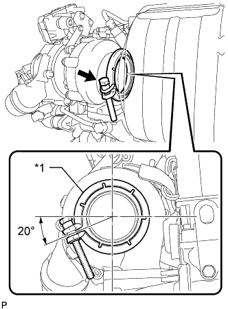
Text in Illustration *1 V-band Clamp Align the V-band clamp as shown in the illustration and temporarily install it.
- Torque:
- 2.0 N*m { 20 kgf*cm, 18 in.*lbf }
Tech Tips
To prevent the V-band clamp from interfering with the No. 1 manifold converter insulator, temporarily install the V-band clamp at the angle shown in the illustration.
-
Tighten the 5 nuts, 2 bolts, V-band clamp and exhaust manifold converter sub-assembly in the order shown in the illustration.
- Torque:
- for bolt
- 38 N*m { 387 kgf*cm, 28 ft.*lbf }
- for nut
- 19 N*m { 194 kgf*cm, 14 ft.*lbf }
- for V-band clamp
- 15 N*m { 153 kgf*cm, 11 ft.*lbf }
-
-
INSTALL NO. 1 EXHAUST MANIFOLD HEAT INSULATOR
-
Install the No. 1 exhaust manifold heat insulator with the 2 bolts.
- Torque:
- 8.0 N*m { 82 kgf*cm, 71 in.*lbf }
-
Attach the 2 clamps and connect the engine wire.
-
-
INSTALL FUEL FEED PIPE SUB-ASSEMBLY
-
Install the fuel feed pipe sub-assembly with the 2 bolts.
Tech Tips
Refer to "SPECIFICATIONS - STANDARD BOLT" for the tightening torque.
-
Connect the 2 fuel hoses to the fuel supply pump assembly, and tighten the 2 clamps to secure the 2 hoses.
-
Connect the fuel return tube to the common rail assembly.
-
Attach the fuel hose clamp.
-
Connect the nozzle leakage pipe assembly to the fuel feed pipe sub-assembly.
-
-
INSTALL INTAKE MANIFOLD
-
Install a new gasket to the No. 2 EGR pipe sub-assembly.
Tech Tips
Make sure that the claw of the gasket faces the No. 2 EGR pipe sub-assembly.
-
Install 4 new gaskets to the intake manifold.
-
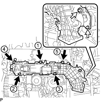
Temporarily install the intake manifold with the 7 bolts.
Text in Illustration Bolt A Bolt B -
Step 1:
Tighten the 5 bolts labeled A of the intake manifold in the order shown in the illustration.
- Torque:
- 5.0 N*m { 51 kgf*cm, 44 in.*lbf }
-
Step 2:
Tighten the 5 bolts labeled A in the order shown in the illustration again.
- Torque:
- 10 N*m { 102 kgf*cm, 7 ft.*lbf }
-
Step 3:
Tighten the 2 bolts labeled B.
- Torque:
- 8.0 N*m { 82 kgf*cm, 71 in.*lbf }
-
-
INSTALL NO. 1 VACUUM PIPE
-
Install a new O-ring to the No. 1 vacuum pipe.
-
Using an E7 "TORX" socket wrench, install the No. 1 vacuum pipe with the bolt to the cylinder block sub-assembly.
- Torque:
- 8.0 N*m { 82 kgf*cm, 71 in.*lbf }
-
Connect the vacuum hose.
-
-
INSTALL NO. 2 VACUUM HOSE ASSEMBLY
-
Install the No. 2 vacuum hose assembly to the No. 2 engine hanger with the bolt and nut.
- Torque:
- 8.5 N*m { 87 kgf*cm, 75 in.*lbf }
-
-
CONNECT NO. 2 VACUUM HOSE ASSEMBLY
-
Connect the No. 2 vacuum hose assembly to the No. 1 vacuum pipe.
-
Check that there is no damage or contamination in the connected part of the No. 1 vacuum pipe.
-
Line up the No. 1 vacuum pipe and No. 2 vacuum hose assembly connector and push them together until a "click" sound is heard. If the connection is tight, apply a small amount of clean engine oil to the tip of the No. 1 vacuum pipe.
-
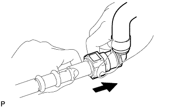
After connecting the No. 1 vacuum pipe and No. 2 vacuum hose assembly connector, check that the No. 1 vacuum pipe and No. 2 vacuum hose assembly connector are securely connected by pulling on them.
Text in Illustration Pull
-
-
-
INSTALL ENGINE OIL LEVEL DIPSTICK GUIDE
-
Install a new O-ring to the engine oil level dipstick guide.
-
Using a T25 "TORX" socket wrench, install the engine oil level dipstick guide with the bolt.
Tech Tips
Refer to "SPECIFICATIONS - STANDARD BOLT" for the tightening torque.
-
Attach the clamp and connect the fuel feed pipe sub-assembly to the engine oil level dipstick guide.
-
Install the engine oil level dipstick.
-
-
INSTALL DIESEL THROTTLE BODY ASSEMBLY
-
Connect the diesel throttle body assembly connector.
-
Install a new gasket to the air tube assembly.
-
Attach the 2 claws and install the air tube assembly to the diesel throttle body assembly.
-
Install a new gasket and the diesel throttle body assembly with air tube assembly with the 3 bolts.
- Torque:
- 8.0 N*m { 82 kgf*cm, 71 in.*lbf }
-
Install the bolt and connect the air tube assembly to the cylinder block sub-assembly.
Tech Tips
Refer to "SPECIFICATIONS - STANDARD BOLT" for the tightening torque.
-
Attach the clamp and connect the No. 7 engine wire connector.
-
Connect the intake air temperature sensor connector.
-
Attach the water by-pass hose assembly and radiator hose sub-assembly to the air tube assembly.
-
-
INSTALL V-RIBBED BELT TENSIONER ASSEMBLY
-
Install the V-ribbed belt tensioner assembly with the 2 bolts.
- Torque:
- 20 N*m { 204 kgf*cm, 15 ft.*lbf }
-
-
INSTALL ENGINE MOUNTING BRACKET
-
Install the stud bolt to the engine mounting bracket.
- Torque:
- 13 N*m { 127 kgf*cm, 9 ft.*lbf }
-
Using an E12 "TORX" socket wrench, install the engine mounting bracket with the 3 bolts.
- Torque:
- 59 N*m { 602 kgf*cm, 44 ft.*lbf }
-
-
INSTALL IDLER PULLEY ASSEMBLY
-
Using a T50 "TORX" socket wrench, tighten the bolt to install the idler pulley assembly.
- Torque:
- 40 N*m { 408 kgf*cm, 30 ft.*lbf }
-
-
INSTALL GENERATOR ASSEMBLY
-
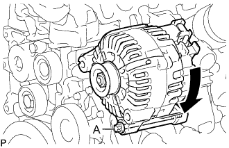
Установите генератор в сборе и закрепите его 2 болтами с помощью торцевого ключа "TORX" Е12.
- Torque:
- 38 Н*м { 387 кгс*см, 28 фунт-сила-футов }
Tech Tips
Установите генератор в сборе, когда болт A вставлен, как показано на рисунке.
-
Подсоедините провод генератора и зафиксируйте соединение гайкой.
- Torque:
- 13 Н*м { 129 кгс*см, 9 фунт-сила-футов }
-
Установите заглушку контакта.
-
Подсоедините разъем генератора.
-
-
INSTALL COMPRESSOR ASSEMBLY WITH PULLEY (w/ Air Conditioning System)
-
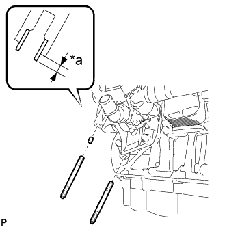
Обозначения на рисунке *a Высота выступания С помощью молотка с пластмассовым покрытием установите новый штифт компрессора.
Номинальная высота выступа 3,5-4,5 мм (0,138-0,177 дюйма) -
С помощью торцевого ключа "TORX" Е8 вверните 2 резьбовые шпильки.
- Torque:
- 9,8 Н*м { 100 кгс*см, 87 фунт-сила-дюймов }
-
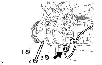
Вверните болт и 2 гайки.
- Torque:
- 25 Н*м { 255 кгс*см, 18 фунт-сила-футов }
Tech Tips
Затягивайте болты и гайки в порядке, показанном на рисунке.
-
Подсоедините разъем и зажим жгута проводов.
-
-
INSTALL FAN AND GENERATOR V BELT
-
Rotate the pulley of the V-ribbed belt tensioner assembly clockwise, and then install the fan and generator V belt.
Note
Make sure that the fan and generator V belt is set properly on each pulley.
-
-
CONNECT ENGINE WIRE
-
INSTALL ENGINE COVER