БЛОК ДВИГАТЕЛЯ ПОВТОРНАЯ СБОРКА

Note
-
Always be sure to check the tightening torque.
-
If the pressure lines are leaking after installation, they must be replaced.
-
Do not overtighten the pressure lines.
-
All pressure lines may only be reused 3 times. After the 3rd time, they must be replaced.
-
INSTALL NO. 2 OIL NOZZLE SUB-ASSEMBLY
-
Using an E8 "TORX" socket wrench, install the No. 2 oil nozzle sub-assembly with the bolt.
- Torque:
- 10 N*m { 102 kgf*cm, 7 ft.*lbf }
-
-
INSTALL INJECTION PUMP DRIVE GEAR
-
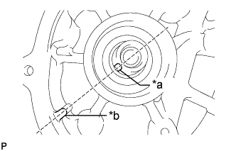
Text in Illustration *a Cutout *b Protrusion Align the cutout of the fuel supply pump assembly with the protrusion of the cylinder block and temporarily install the fuel supply pump with the 2 bolts.
-
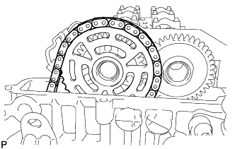
Set the chain sub-assembly to the crankshaft.
-
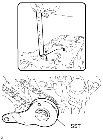
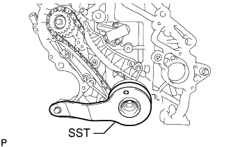
Text in Illustration *a 0.5 to 1.0 mm (0.0197 to 0.0394 in.) Install SST by rotating the crankshaft as shown in the illustration.
SST PZ4TB-04964-42 Tech Tips
The No. 1 piston position is 0.5 to 1.0 mm (0.0197 to 0.0394 in.) lower than the top of the cylinder block.
-
Install the injection pump drive gear with the chain sub-assembly.
-
Install the fuel supply pump assembly with the 2 bolts.
- Torque:
- 19 N*m { 194 kgf*cm, 14 ft.*lbf }
-
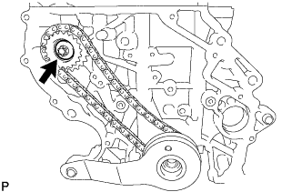
Install the central bolt to the injection pump drive gear
- Torque:
- 65 N*m { 663 kgf*cm, 48 ft.*lbf }
-
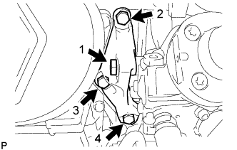
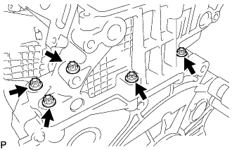
Temporarily install the fuel supply pump assembly support with the 4 bolts by hand in the order shown in the illustration.
-
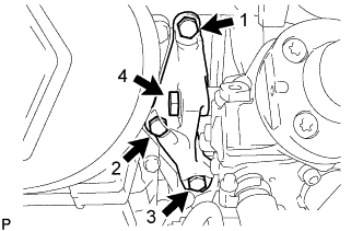
Tighten the 4 bolts in the order shown in the illustration.
- Torque:
- 19 N*m { 194 kgf*cm, 14 ft.*lbf }
-
-
INSTALL TIMING CHAIN GUIDE
-
Using a T45 "TORX" socket wrench, install the timing chain guide with the 2 bolts.
- Torque:
- 20 N*m { 204 kgf*cm, 15 ft.*lbf }
-
-
INSTALL TIMING CHAIN TENSION ARM
-
Using a T45 "TORX" socket wrench, install the timing chain tension arm with the bolt.
- Torque:
- 20 N*m { 204 kgf*cm, 15 ft.*lbf }
-
-
INSTALL NO. 1 CHAIN TENSIONER ASSEMBLY
-
Using an E8 "TORX" socket wrench, install the No. 1 chain tensioner assembly with the 2 bolts.
- Torque:
- 10 N*m { 102 kgf*cm, 7 ft.*lbf }
-
Remove the 3.0 mm hexagon wrench from the No. 1 chain tensioner assembly.
-
Remove SST.
SST PZ4TB-04964-42
-
-
INSTALL NO. 2 TIMING CHAIN TENSION ARM
-
Using a T45 "TORX" socket wrench, install the No. 2 timing chain tension arm with the bolt.
- Torque:
- 20 N*m { 204 kgf*cm, 15 ft.*lbf }
-
-
INSTALL NO. 2 CHAIN SUB-ASSEMBLY
-
Install the No. 2 chain sub-assembly to the injection pump drive gear.
-
-
INSTALL OIL PUMP DRIVE CHAIN SUB-ASSEMBLY
-
Install the oil pump drive chain sub-assembly to the crankshaft.
-
-
INSTALL TIMING CHAIN COVER PLATE
-
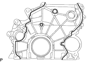
Apply seal packing in a continuous line as shown in the illustration.
Standard seal diameter 1.5 to 2.0 mm (0.0590 to 0.0787 in.) Note
-
Remove any oil from the contact surface.
-
Install the timing chain cover plate within 3 minutes after applying seal packing.
-
Do not start the engine for at least 4 hours after installation.
-
-
Using an E8 "TORX" socket wrench, install the timing chain cover plate with the 11 bolts.
- Torque:
- 20 N*m { 204 kgf*cm, 15 ft.*lbf }
-
Apply a light coat of engine oil to a new O-ring, and install it to the sealing cap.
-
Install the sealing cap to the timing case housing.
- Torque:
- 20 N*m { 204 kgf*cm, 15 ft.*lbf }
-
-
INSTALL REAR ENGINE OIL SEAL
-
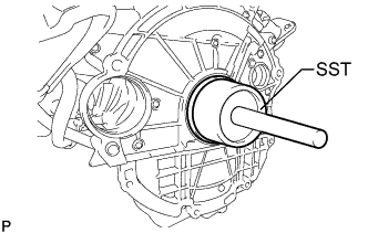
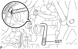
Using SST, tap in a new rear engine oil seal until its surface is flush with the rear oil seal retainer edge.
- SST
- 09608-36010
- 09950-70010 ( 09951-07100 )
Note
Do not tap the rear engine oil seal at an angle.
-
-
INSTALL OIL PUMP WITH VACUUM PUMP ASSEMBLY
-
Install the oil pump drive chain sub-assembly to the oil pump drive shaft gear, and then install the oil pump with vacuum pump assembly.
-
Using an E10 "TORX" socket wrench, install the oil pump with vacuum pump assembly with the 4 bolts.
- Torque:
- 20 N*m { 204 kgf*cm, 15 ft.*lbf }
-
-
INSTALL OIL STRAINER SUB-ASSEMBLY
-
Install the oil strainer sub-assembly with the 2 bolts.
Tech Tips
Refer to "SPECIFICATIONS - STANDARD BOLT" for the tightening torque.
-
-
INSTALL OIL PAN SUB-ASSEMBLY
-
Remove any old seal packing material.
-
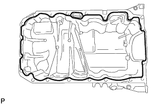
Apply seal packing to the oil pan sub-assembly as shown in the illustration.
Standard seal packing diameter 2.0 to 2.5 mm (0.0787 to 0.0984 in.) Note
-
Remove any oil from the contact surface.
-
After applying seal packing, install the oil pan sub-assembly within 3 minutes and tighten the bolts.
-
-
Using an E10 "TORX" socket wrench, temporarily install the oil pan sub-assembly with the 24 bolts.
- Torque:
- 5.0 N*m { 51 kgf*cm, 44 in.*lbf }
-
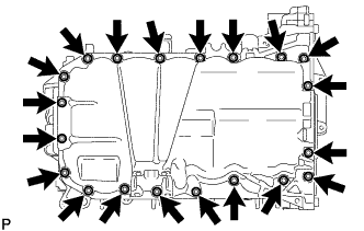
Tighten the 20 bolts.
- Torque:
- 20 N*m { 204 kgf*cm, 15 ft.*lbf }
-
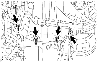
Tighten the 4 bolts.
- Torque:
- 24 N*m { 245 kgf*cm, 18 ft.*lbf }
-
-
INSTALL FLYWHEEL WITH DAMPER ASSEMBLY
-
Install the crankshaft position sensor plate to the crankshaft.
-
Temporarily install the flywheel with damper assembly with 8 new bolts.
-
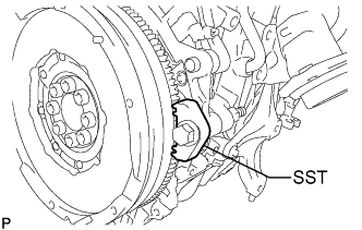
Using SST, fix the flywheel with damper assembly.
SST PZ4TB-04939-38 -
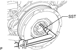
Using SST, tighten the 8 bolts.
SST PZ4TB-04910-18 - Torque:
- 120 N*m { 1224 kgf*cm, 89 ft.*lbf }
-
Remove SST.
-
-
INSTALL CLUTCH DISC ASSEMBLY
-
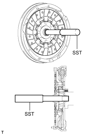
Insert SST into the clutch disc, and then insert them into the flywheel.
- SST
- 09301-00310
Note
Insert the clutch disc with the disc facing in the correct direction.
-
-
INSTALL CLUTCH COVER ASSEMBLY
-
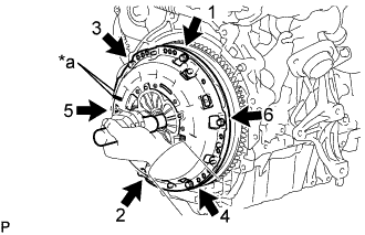
Text in Illustration *a Matchmark Align the matchmark on the clutch cover with the one on the flywheel.
-
Install and tighten the 6 bolts uniformly in the order shown in the illustration, starting with the bolt located near the knock pin on the top.
- Torque:
- 19 N*m { 195 kgf*cm, 14 ft.*lbf }
Note
-
Be sure to uniformly tighten the bolts 180° at a time according to the order in the illustration.
-
Move SST up and down, right and left lightly after checking that the clutch disc assembly is in the center, and then tighten the bolts.
-
-
INSPECT AND ADJUST CLUTCH COVER ASSEMBLY
-
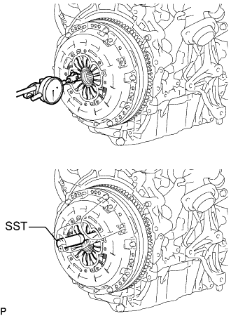
Using a dial indicator with a roller instrument, measure the diaphragm spring tip alignment.
Maximum misalignment 1.3 mm (0.0512 in.) If the misalignment is more than the maximum, using SST, adjust the diaphragm spring tip alignment.
- SST
- 09333-00013
-
-
INSTALL TIMING GEAR CASE OR TIMING CHAIN CASE OIL SEAL
-
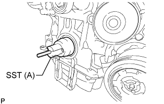
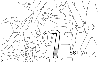
Using an 8 mm hexagon wrench, install SST (A) to the crankshaft.
SST PZ4TB-04961-27 -
Set a new timing gear case or timing chain case oil seal to the cylinder block.
-
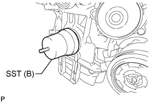
Install SST (B) to SST (A).
SST PZ4TB-04961-27 -
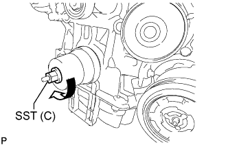
Install and tighten SST (C) to install the timing gear case or timing chain case oil seal to the crankshaft.
SST PZ4TB-04961-27 Tech Tips
Tighten SST (C) until SST (B) contacts the cylinder block.
-
Remove SST (C), SST (B) and SST (A).
-
-
INSTALL CRANKSHAFT PULLEY
-
Using SST, hold the flywheel sub-assembly.
SST PZ4TB-04951-26 -
Install the crankshaft pulley to the crankshaft with 4 new bolts.
Tech Tips
The crankshaft pulley bolts are tightened in 2 progressive steps.
-
Step 1:
-
Using an E10 "TORX" socket wrench, tighten the 4 bolts.
- Torque:
- 40 N*m { 408 kgf*cm, 30 ft.*lbf }
-
-
Step 2:
-
Mark the RH side of the each crankshaft pulley bolt with paint.
-
Tighten the bolts 120°.
-
Check that the paint marks are now at a 120° angle to the RH side.
-
-
Remove SST.
-
Install the plug to the cylinder block.
-
-
SELECT CYLINDER HEAD GASKET
-
Check the piston protrusions for each cylinder.
-
Clean the cylinder block with solvent.
-
Set the piston of the cylinder to be measured to slightly before TDC.
-
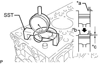
Text in Illustration *a Measuring Tip *b Measuring Point *c Protrusion Using SST, place a dial indicator on the cylinder block and set the measuring tip as shown in the illustration.
SST PZ4TB-04901-85 -
Set the dial indicator at 0 mm (0 in.).
Tech Tips
Make sure that the measuring tip is perpendicular to the cylinder head gasket surface and piston head when taking the measurements.
-
Find where the piston head protrudes most by slowly turning the crankshaft clockwise and counterclockwise.
-
Measure each cylinder at 2 places for a total of 8 measurements.
-
For the piston protrusion value of each cylinder, use the average of the 2 measurements of each cylinder.
Standard piston protrusion 0.420 to 0.680 mm (0.0165 to 0.0267 in.) If the protrusion is not as specified, remove the piston sub-assembly and connecting rod sub-assembly and reinstall them.
-
-
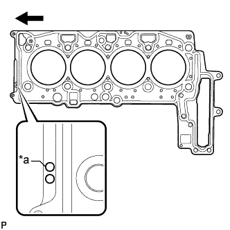
Text in Illustration *a Cylinder Head Gasket Hole 
Front Select a new cylinder head gasket.
New Installed Cylinder Head Gasket Thickness Cylinder Head Gasket Holes Specified Condition 1 Hole 0.95 mm (0.0374 in.) 2 Holes 1.05 mm (0.0413 in.) 3 Holes 1.15 mm (0.0452 in.) Tech Tips
Cylinder head gaskets have 1, 2, or 3 holes.
-
Select the largest piston protrusion value from the measurements and then select a new appropriate gasket according to the table below.
Cylinder Head Gasket Size Item Specified Condition Piston Protrusion 0.42 mm (0.0165 in.) or less 0.42 to 0.53 mm (0.0165 to 0.0208 in.) 0.53 to 0.68 mm (0.0208 to 0.0267 in.) Cylinder Head Gasket Holes 1 Hole 2 Holes 3 Holes
-
-
-
INSTALL CYLINDER HEAD GASKET
-
Place the cylinder head gasket in position on the cylinder block.
-
-
INSTALL CYLINDER HEAD SUB-ASSEMBLY
Note
-
Do not reuse the cylinder head bolts.
-
Make sure the ring pin shown in the illustration is not loose, deformed or otherwise damaged.
-
Place the cylinder head sub-assembly on the cylinder head gasket.
Note
Be careful of the installation direction.
-
Using an E10 "TORX" socket wrench, temporarily install the 5 bolts.
-
Apply a light coat of engine oil to under the heads of the new cylinder head bolts.
Note
Do not reuse the cylinder head bolts.
-
Temporarily install the new cylinder head bolts.
-
Step 1:
-
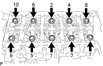
Using an E18 "TORX" socket wrench, uniformly tighten the 10 cylinder head bolts in several steps in the sequence shown in the illustration.
- Torque:
- 70 N*m { 714 kgf*cm, 52 ft.*lbf }
-
Mark the front of each cylinder head bolts head with paint.
-

Loosen the cylinder head bolts by 180° in the sequence shown in the illustration.
-
-
Step 2:
-
Tighten the 10 cylinder head bolts in several steps in the sequence shown in the illustration.
- Torque:
- 50 N*m { 510 kgf*cm, 37 ft.*lbf }
-
Retighten the cylinder head bolts by 120°.
-
-
Step 3:
-
Tighten the cylinder head bolts 120° further.
-
Check that the paint marks are now at a 240° angle to the RH.
-
-
Using an E10 "TORX" socket wrench, tighten the 5 bolts.
- Torque:
- 10 N*m { 102 kgf*cm, 7 ft.*lbf }
-
-
INSPECT VALVE LASH ADJUSTER ASSEMBLY
Note
-
Keep the valve lash adjuster free from dirt and foreign objects.
-
Use only clean engine oil.
-
Place the valve lash adjuster assembly into a container full of new engine oil.
-
Insert SST tip into the valve lash adjuster plunger and use the tip to press down on the check ball inside the plunger.
- SST
- 09276-75010
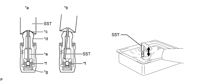
Text in Illustration *a CORRECT *b INCORRECT *c Taper Port *d Plunger *e Lower Pressure Chamber *f Check Ball *g High Pressure Chamber - - -
Squeeze SST and the valve lash adjuster together to move the plunger up and down 5 to 6 times.
-
Check the movement of the plunger and bleed air.
OK Plunger moves up and down. Note
When bleeding high-pressure air from the compression chamber, make sure that the tip of SST is actually pressing the check ball as shown in the illustration. If the check ball is not pressed, air will not bleed.
-
After bleeding air, remove SST. Then quickly and firmly press the plunger repeatedly with your fingers.
OK Plunger can be pressed 3 times. If the plunger can still be compressed after pressing it 3 times, replace the valve lash adjuster assembly with a new one.
-
-
INSTALL VALVE LASH ADJUSTER ASSEMBLY
-
Install the 16 valve lash adjuster assemblies to the cylinder head sub-assembly.
Note
Install the valve lash adjuster assemblies to their original positions.
-
-
INSTALL NO. 1 VALVE ROCKER ARM SUB-ASSEMBLY
-
Install the 16 No. 1 valve rocker arm sub-assemblies.
-
-
INSTALL CAMSHAFT HOUSING SUB-ASSEMBLY
-
Install 4 new gaskets.
-
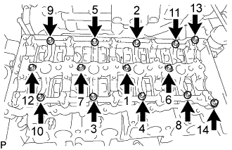
Uniformly tighten the 14 bolts in several steps in the sequence shown in the illustration.
-
Using an E10 "TORX" socket wrench, install camshaft housing sub-assembly with the 14 bolts.
- Torque:
- 13 N*m { 133 kgf*cm, 10 ft.*lbf }
-
-
SET NO. 1 CYLINDER TO TDC/COMPRESSION
-
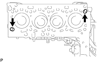
Remove the plug from the cylinder block.
-
Set SST (A) to the plug hole of the cylinder block.
SST(A) PZ4TB-04951-26 -
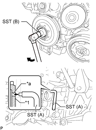
Text in Illustration *1 Flywheel with Damper Assembly *a Groove Using SST (B), turn the crankshaft pulley clockwise until SST(A) fits into the groove of the flywheel with damper assembly.
SST (B) PZ4TB-04933-80 -
Using SST(A), hold the flywheel with damper assembly.
SST (A) PZ4TB-04951-26 -
Remove SST.
-
Install the plug to the cylinder block.
-
-
INSTALL CAMSHAFT AND NO. 2 CAMSHAFT
-
Apply clean engine oil to the cam lobe of each camshaft, journals of the camshaft housing sub-assembly and No. 1 valve rocker arm sub-assemblies.
-
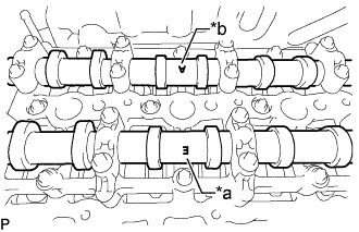
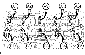
Place the camshaft and No. 2 camshaft on the camshaft housing sub-assembly as shown in the illustration so that mark E and mark A face upward.
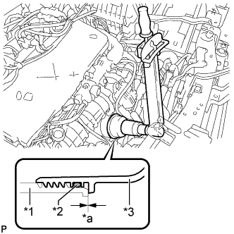
Text in Illustration *a Mark E (Intake Side) *b Mark A (Exhaust Side) Note
Before and after setting the camshaft and No. 2 camshaft on the camshaft housing sub-assembly, check that the No. 1 valve rocker arm sub-assembly is firmly set to the valve lash adjuster assembly.
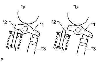
Text in Illustration *1 No. 1 Valve Rocker Arm Sub-assembly *2 Valve Stem *3 Valve Lash Adjuster Assembly *a CORRECT *b INCORRECT -
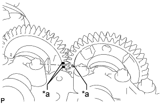
Text in Illustration *a Timing Mark Align the camshaft and No. 2 camshaft timing marks.
-
Set the 5 intake camshaft bearing caps and 5 exhaust camshaft bearing caps on the camshaft and No. 2 camshaft as shown in the illustration.
-
Using an E8 "TORX" socket wrench, partially tighten the 20 bolts.
-
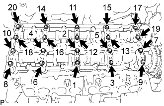
Uniformly tighten the 20 bolts in several steps in the sequence shown in the illustration.
- Torque:
- 10 N*m { 102 kgf*cm, 7 ft.*lbf }
-
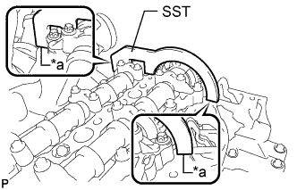
Text in Illustration *a No clearance Using SST, hold the camshaft and No. 2 camshaft.
SST PZ4TB-04961-12 Note
Make sure there is no clearance between SST and the camshaft housing sub-assembly.
-
Using an E10 "TORX" socket wrench, temporarily install the camshaft timing sprocket with No. 2 chain sub-assembly to the camshaft with the 3 bolts.
-
Step 1:
Tighten the 3 bolts.
- Torque:
- 10 N*m { 102 kgf*cm, 7 ft.*lbf }
-
Step 2:
Loosen the 3 bolts 90°.
-
-
Using a T45 "TORX" socket wrench, install the No. 2 timing chain guide with the bolt.
- Torque:
- 20 N*m { 204 kgf*cm, 15 ft.*lbf }
-
Using a 24 mm socket wrench, install the No. 2 chain tensioner assembly.
- Torque:
- 70 N*m { 714 kgf*cm, 52 ft.*lbf }
-
Using an E10 "TORX" socket wrench, install the camshaft timing sprocket with the 3 bolts.
- Torque:
- 14 N*m { 143 kgf*cm, 10 ft.*lbf }
-
Remove SST from the camshaft.
-
-
INSTALL CYLINDER HEAD COVER SUB-ASSEMBLY
-
Install 5 new gaskets to the cylinder head cover sub-assembly.
-
Install the cylinder head cover sub-assembly and tighten the 17 bolts.
Tech Tips
Refer to "SPECIFICATIONS - STANDARD BOLT" for the tightening torque.
-
-
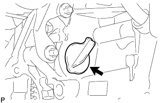
INSTALL OIL FILLER CAP SUB-ASSEMBLY
-
INSTALL OIL FILTER ASSEMBLY
-
Install a new gasket to the oil filter assembly.
-
Install the oil filter assembly with the 6 bolts.
- Torque:
- 25 N*m { 255 kgf*cm, 18 ft.*lbf }
-
-
INSTALL OIL FILTER SUB-ASSEMBLY
-
Clean the inside of the oil filter cover, its threads and its O-ring.
-
Text in Illustration *1 O-Ring *a CORRECT *b INCORRECT Apply a small amount of engine oil to a new O-ring and install it to the oil filter cover.
Note
-
Be sure to install the O-ring in the proper location, otherwise oil may leak.
-
Do not twist the O-ring.
-
-
Apply a light coat of engine oil to a new O-ring.
-
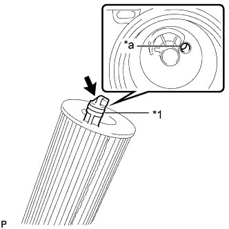
Text in Illustration *1 O-Ring *a Oil Filter Assembly Hole Protrusion Install the O-ring to the oil filter sub-assembly.
-
Set a new oil filter sub-assembly in the oil filter assembly.
Note
Insert the protrusion of the oil filter sub-assembly into the oil filter assembly hole.
-
Apply a small amount of engine oil to the O-ring again and temporarily install the oil filter cover.
-
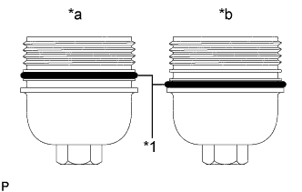
Text in Illustration *1 Oil Filter Assembly *2 O-Ring *3 Oil Filter Cover *a No Gap Using a 27 mm socket wrench, tighten the oil filter cover.
- Torque:
- 25 N*m { 255 kgf*cm, 18 ft.*lbf }
Note
After tightening the oil filter cover, make sure that there is no gap and that the O-ring is not protruding.
-
-
INSTALL WATER OUTLET
-
Install a new gasket to the water outlet.
-
Using an E10 "TORX" socket wrench, install the water outlet with the 3 bolts.
- Torque:
- 10 N*m { 102 kgf*cm, 7 ft.*lbf }
-
-
INSTALL WATER INLET HOUSING
-
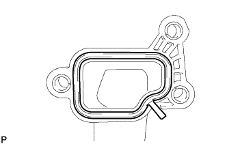
Apply seal packing in a continuous line as shown in the illustration.
Standard seal diameter 2.0 to 2.5 mm (0.0787 to 0.0984 in.) Note
-
Remove any oil from the contact surface.
-
Install the water inlet housing within 3 minutes after applying seal packing.
-
Do not start the engine for at least 4 hours after installation.
-
-
Using an E11 "TORX" socket wrench, install the water inlet housing with the 5 bolts.
- Torque:
- 20 N*m { 204 kgf*cm, 15 ft.*lbf }
-
-
INSTALL THERMOSTAT
-
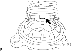
Align the jiggle valve with the top of the water inlet to install the jiggle valve.
-
-
INSTALL WATER INLET
-
Temporarily install the water inlet together with the thermostat with the 4 bolts by hand.
-
Using several steps, uniformly tighten the 4 bolts.
Tech Tips
Refer to "SPECIFICATIONS - STANDARD BOLT" for the tightening torque.
-
-
INSTALL WATER BY-PASS PIPE
-
Using a 5 mm hexagon socket wrench, install the water by-pass pipe to the water inlet housing with the bolt.
Tech Tips
Refer to "SPECIFICATIONS - STANDARD BOLT" for the tightening torque.
-
-
INSTALL ENGINE WATER PUMP ASSEMBLY
-
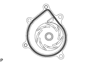
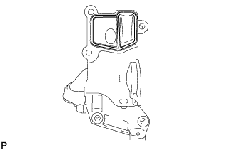
Apply seal packing in a continuous line as shown in the illustration.
Standard seal diameter 2.0 to 2.5 mm (0.0787 to 0.0984 in.) Note
-
Remove any oil from the contact surface.
-
Install the engine water pump assembly within 3 minutes after applying seal packing.
-
Do not start the engine for at least 4 hours after installation.
-
-
Install the engine water pump assembly with the 5 bolts.
- Torque:
- 10 N*m { 102 kgf*cm, 7 ft.*lbf }
-
-
INSTALL INJECTOR ASSEMBLY
Note
-
Before installing the injector assembly, check for carbon, foreign matter, etc. on the seal surfaces of the cylinder head sub-assembly and injector assembly. If there is foreign matter, remove it before installing the injector assembly.
-
Make sure to replace the copper sealing ring on the injector assembly.
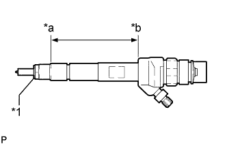
Text in Illustration *1 Copper Sealing Ring *a Point Above the Copper Sealing Ring *b Injector Assembly Slot End -
Before installing the injector assemblies to the injector assembly slots, apply a light coat of highly heat-resistant grease from above the top of the copper sealing ring to the injector assembly slot end.
-
Check the installation position of the high pressure connection.
-
Make sure to read the adjustment values each time new injector assemblies are installed.
Tech Tips
Perform "Inspection After Repairs" after replacing the fuel injector assembly Click here.
-
Install the 4 injector assemblies to the cylinder head cover sub-assembly.
-
Using an E10 "TORX" socket wrench, install the 4 clamping claws to the 4 injector assemblies with the 4 centering rings and 4 bolts.
- Torque:
- 10 N*m { 102 kgf*cm, 7 ft.*lbf }
Note
-
Retighten the clamping claw (cylinder head cover mounting).
-
Make sure the screw centering ring is correctly positioned in order to align the clamping claw.
-
Connect the 4 injector assembly connectors.
-
-
INSTALL NOZZLE LEAKAGE PIPE ASSEMBLY
-
Install 4 new sealing rings and connect the nozzle leakage pipe assembly.
-
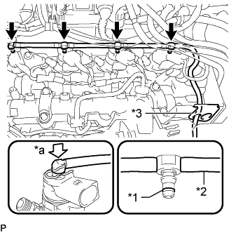
Text in Illustration *1 Sealing Ring *2 Leakage Line *3 Rubber Grommet *a Downward Connect the nozzle leakage pipe assembly to the rubber grommet.
-
Install 4 new sealing rings to the nozzle leakage pipe assembly.
-
Attach the connection of the nozzle leakage pipe assembly downwards.
-
-
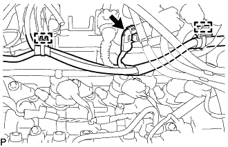
Connect the connector and attach the 2 clamps to connect the wire harness.
-
-
INSTALL ENGINE OIL PRESSURE SWITCH ASSEMBLY
-
Install a new gasket.
-
Using a 24 mm deep socket wrench, install the engine oil pressure switch assembly.
- Torque:
- 28 N*m { 280 kgf*cm, 20 ft.*lbf }
-
Connect the engine oil pressure switch connector.
-
-
INSTALL ENGINE COOLANT TEMPERATURE SENSOR
-
Using a 17 mm (12P) deep socket wrench, install the engine coolant temperature sensor.
- Torque:
- 3.5 N*m { 36 kgf*cm, 31 ft.*lbf }
-
Connect the engine coolant temperature sensor connector.
-
-
INSTALL CRANKSHAFT POSITION SENSOR
-
Connect the crankshaft position sensor connector.
-
Using a T25 "TORX" socket wrench, install the crankshaft position sensor with the bolt.
- Torque:
- 6.0 N*m { 61 kgf*cm, 53 in.*lbf }
-
-
INSTALL CAMSHAFT POSITION SENSOR
-
Apply a light coat of engine oil to the O-ring of the camshaft position sensor.
Note
-
When reusing the camshaft position sensor, inspect the O-ring.
-
Make sure that the O-ring is not cracked or jammed when installing the camshaft position sensor.
-
-
Using an E6 "TORX" socket wrench, install the camshaft position sensor with the bolt.
- Torque:
- 3.6 N*m { 37 kgf*cm, 32 in.*lbf }
-
Connect the camshaft position sensor connector.
-