БЛОК ДВИГАТЕЛЯ ПРОВЕРКА

-
INSPECT NO. 1 CHAIN TENSIONER ASSEMBLY
-
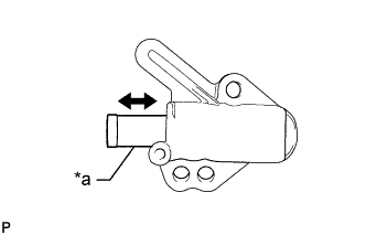
Text in Illustration *a Plunger Push the plunger and check that it moves smoothly.
If necessary, replace the No. 1 chain tensioner assembly.
-
-
INSPECT NO. 2 CHAIN TENSIONER ASSEMBLY
-
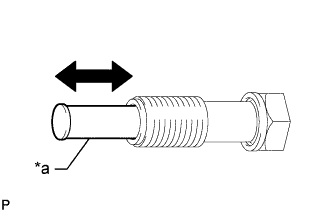
Text in Illustration *a Plunger Push the plunger and check that it moves smoothly.
If necessary, replace the No. 2 chain tensioner assembly.
-
-
INSPECT IDLER PULLEY ASSEMBLY
-
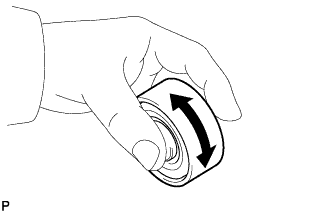
Check that the idler pulley assembly turns smoothly.
If necessary, replace the idler pulley assembly.
-
-
INSPECT CAMSHAFT
-
Check the camshaft for runout.
-
Place the camshaft on V-blocks.
-
Using a dial indicator, measure the circle runout at the center journal.
Maximum circle runout 0.03 mm (0.00118 in.) If the circle runout is more than the maximum, replace the camshaft.
-
-
-
INSPECT NO. 2 CAMSHAFT
-
Check the No. 2 camshaft for runout.
-
Place the camshaft on V-blocks.
-
Using a dial indicator, measure the circle runout at the center journal.
Maximum circle runout 0.03 mm (0.00118 in.) If the circle runout is more than the maximum, replace the No. 2 camshaft.
-
-
-
INSPECT NO. 2 OIL NOZZLE SUB-ASSEMBLY
-
Check the No. 2 oil nozzle sub-assembly for damage or clogging.
If there is damage or clogging, replace the No. 2 oil nozzle sub-assembly.
-
-
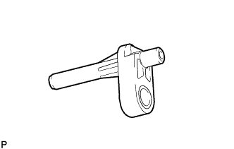
INSPECT NO. 1 VALVE ROCKER ARM SUB-ASSEMBLY
-
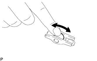
Turn the roller by hand to check that it turns smoothly.
If the roller does not turn smoothly, replace the No. 1 valve rocker arm sub-assembly.
-
-
INSPECT VALVE LASH ADJUSTER ASSEMBLY
Note
-
Keep the valve lash adjuster free from dirt and foreign objects.
-
Use only clean engine oil.
-
Place the valve lash adjuster assembly into a container full of new engine oil.
-
Insert SST tip into the valve lash adjuster plunger and use the tip to press down on the check ball inside the plunger.
- SST
- 09276-75010
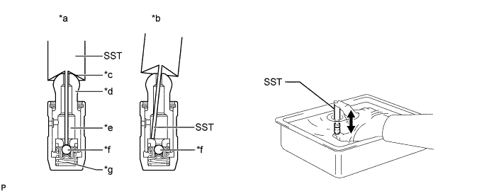
Text in Illustration *a CORRECT *b INCORRECT *c Taper Port *d Plunger *e Lower Pressure Chamber *f Check Ball *g High Pressure Chamber - - -
Squeeze SST and the valve lash adjuster together to move the plunger up and down 5 to 6 times.
-
Check the movement of the plunger and bleed air.
OK Plunger moves up and down. Note
When bleeding high-pressure air from the compression chamber, make sure that the tip of SST is actually pressing the check ball as shown in the illustration. If the check ball is not pressed, air will not bleed.
-
After bleeding air, remove SST. Then quickly and firmly press the plunger repeatedly with your fingers.
OK Plunger can be pressed 3 times. If the plunger can still be compressed after pressing it 3 times, replace the valve lash adjuster assembly with a new one.
-