БЛОК ДВИГАТЕЛЯ РАЗБОРКА
Note
-
After the engine has stopped, wait at least 1 minute before releasing the high pressure lines.
-
When working on the fuel circuit, protect the generator assembly against dirt contamination. Cover generator assembly with suitable materials. Failure to comply with this procedure may result in a generator assembly malfunction.
-
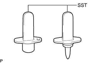
After disconnecting the pressure line, it is absolutely essential to seal the injector assemblies and the common rail assembly with SST.
SST PZ4TB-04941-79
-
REMOVE CAMSHAFT POSITION SENSOR
-
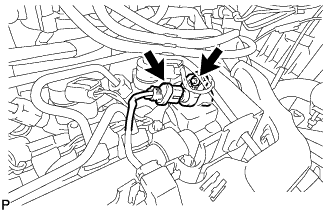
Disconnect the camshaft position sensor connector.
-
Using an E6 "TORX" socket wrench, remove the bolt and camshaft position sensor.
-
-
REMOVE CRANKSHAFT POSITION SENSOR
-
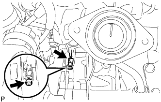
Using a T25 "TORX" socket wrench, remove the bolt.
-
Disconnect the crankshaft position sensor connector and remove the crankshaft position sensor.
-
-
REMOVE ENGINE COOLANT TEMPERATURE SENSOR
-
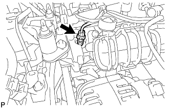
Disconnect the engine coolant temperature sensor connector.
-
Using a 17 mm (12P) deep socket wrench, remove the engine coolant temperature sensor.
-
-
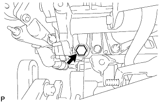
REMOVE ENGINE OIL PRESSURE SWITCH ASSEMBLY
-
Disconnect the engine oil pressure switch assembly connector.
-
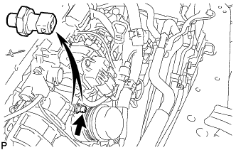
Using a 24 mm deep socket wrench, remove the engine oil pressure switch assembly.
-
Remove the gasket.
-
-
REMOVE NOZZLE LEAKAGE PIPE ASSEMBLY
-
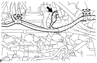
Disconnect the connector and detach the 2 clamps to disconnect the wire harness Click here.
-
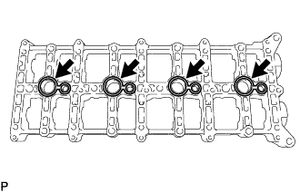
Disconnect the nozzle leakage pipe assembly and remove the 4 sealing rings.
-
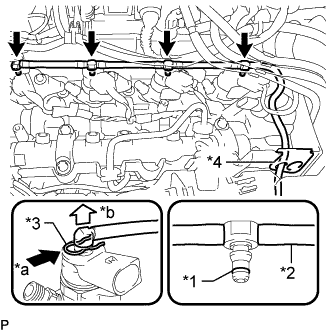
Text in Illustration *1 Sealing Ring *2 Leakage Line *3 Clamp *4 Rubber Grommet *a Press *b Upward Press in the clamp.
Note
If a sealing ring is damaged, the entire leakage line of a cylinder group must be replaced.
-
Detach the connection of the nozzle leakage pipe assembly upwards.
-
Remove the sealing ring.
-
Disconnect the nozzle leakage pipe assembly from the rubber grommet.
-
-
-
REMOVE INJECTOR ASSEMBLY
-
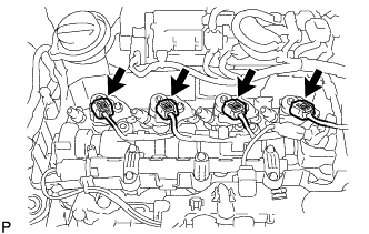
Disconnect the 4 injector assembly connectors.
-
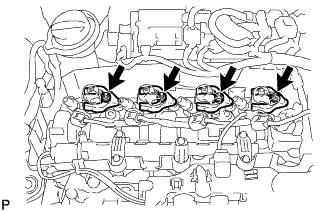
Using an E10 "TORX" socket wrench, remove the 4 bolts and 4 centering rings.
-
Remove the 4 clamping claws from the 4 injector assemblies.
-
Remove the 4 injector assemblies from the cylinder head cover sub-assembly.
-
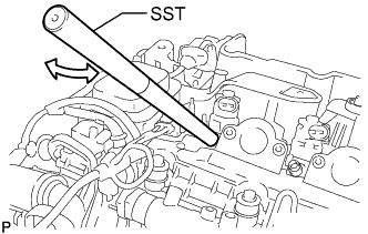
Pull out the injector assembly with light rotational movements.
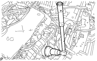
SST PZ4TB-04942-79 Tech Tips
-
If an injector assembly is stuck tight, mount SST (rod) to the pressure line connection.
-
Move injector assembly with SST (rod) only by a few degrees.
-
-
-
-
REMOVE ENGINE WATER PUMP ASSEMBLY
-
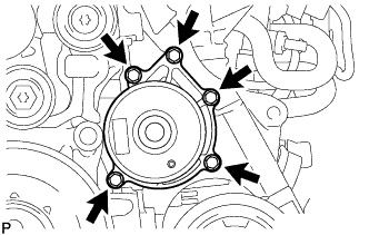
Remove the 5 bolts, engine water pump assembly.
-
-
REMOVE WATER BY-PASS PIPE
-
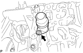
Using a 5 mm hexagon socket wrench, remove the bolt and water by-pass pipe from the water inlet housing.
-
-
REMOVE WATER INLET
-
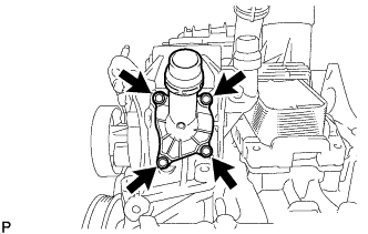
Remove the 4 bolts and water inlet together with the thermostat.
-
Remove the gasket from the water inlet.
-
-
REMOVE THERMOSTAT
-
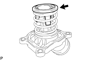
Remove the thermostat.
-
-
REMOVE WATER INLET HOUSING
-
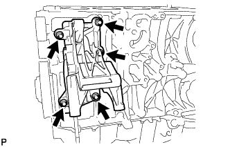
Using an E11 "TORX" socket wrench, remove the 5 bolts and water inlet housing.
-
-
REMOVE WATER OUTLET
-
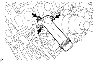
Using an E10 "TORX" socket wrench, remove the 3 bolts and water outlet.
-
Remove the gasket from the water outlet.
-
-
REMOVE OIL FILTER SUB-ASSEMBLY
-
Using a 27 mm socket wrench, remove the oil filter cover.
-
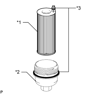
Text in Illustration *1 Oil Filter Sub-assembly *2 Oil Filter Cover *3 O-Ring Remove the 2 O-rings from the oil filter sub-assembly and the oil filter cover.
Note
Be sure to remove the O-ring by hand without using any tools to prevent damage to the O-ring groove.
-
Remove the oil filter sub-assembly from the oil filter cover.
-
-
REMOVE OIL FILTER ASSEMBLY
-
Remove the 6 bolts and oil filter assembly.
-
Remove the gasket from the oil filter assembly.
-
-
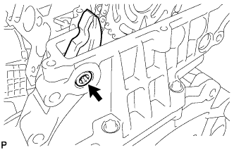
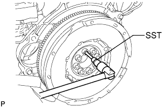
SET NO. 1 CYLINDER TO TDC/COMPRESSION
-
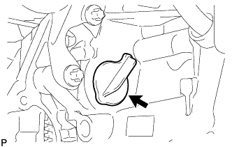
Remove the plug from the cylinder block.
-
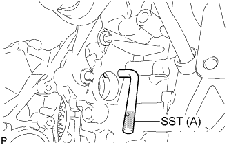
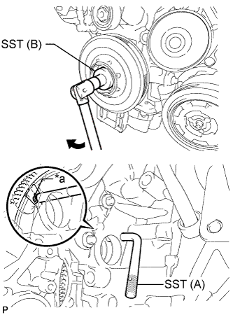
Set SST (A) to the plug hole of the cylinder block.
SST(A) PZ4TB-04951-26 -
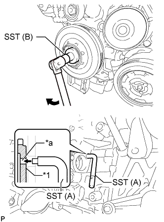
Text in Illustration *1 Flywheel with Damper Assembly *a Groove Using SST (B), turn the crankshaft pulley clockwise until SST(A) fits into the groove of the flywheel with damper assembly.
SST (B) PZ4TB-04933-80 -
Using SST(A), hold the flywheel with damper assembly.
SST (A) PZ4TB-04951-26 -
Remove SST.
-
Install the plug to the cylinder block.
-
-
REMOVE OIL FILLER CAP SUB-ASSEMBLY
-
REMOVE CYLINDER HEAD COVER SUB-ASSEMBLY
-
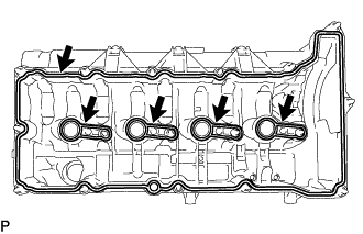
Using an E10 "TORX" socket wrench, loosen the 17 bolts and remove the cylinder head cover sub-assembly.
Tech Tips
Bolt cannot be removed from the cylinder head cover sub-assembly.
-
Remove the 5 gaskets from the cylinder head cover sub-assembly.
-
-
HOLDING CAMSHAFT AND NO. 2 CAMSHAFT
-
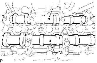
Text in Illustration *a Mark E (Intake Side) *b Mark A (Exhaust Side) Check that the camshaft and No. 2 camshaft on the camshaft housing sub-assembly as shown in the illustration so that mark E and mark A face upward.
Note
If the marks of the camshaft and No. 2 camshaft are not at the positions shown in the illustration, perform set No. 1 cylinder to TDC again.
-
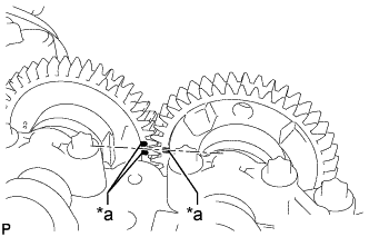
Text in Illustration *a Timing Mark Check the camshaft and No. 2 camshaft timing marks.
-
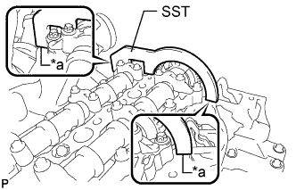
Text in Illustration *a No Clearance Set SST and secure the camshaft and No. 2 camshaft.
SST PZ4TB-04961-12 Note
Make sure there is no clearance between SST and the camshaft housing sub-assembly.
-
-
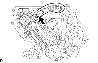
REMOVE NO. 2 CHAIN TENSIONER ASSEMBLY
-
Using a 24 mm socket wrench, remove the No. 2 chain tensioner assembly.
-
-
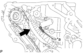
REMOVE NO. 2 TIMING CHAIN GUIDE
-
Using a T45 "TORX" socket wrench, remove the bolt and No. 2 timing chain guide.
-
-
REMOVE CAMSHAFT AND NO. 2 CAMSHAFT
-
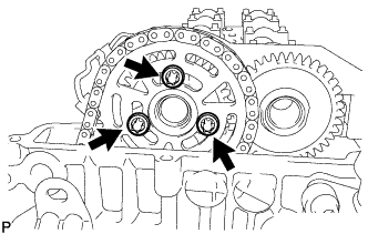
Using an E10 "TORX" socket wrench, remove the 3 bolts and the camshaft timing sprocket.
Note
Do not drop the No. 2 chain sub-assembly into the gap between the cylinder block and timing chain cover plate.
-
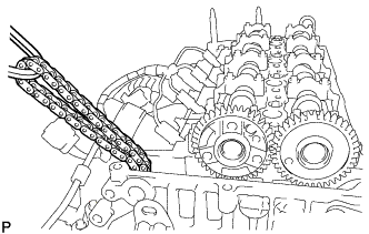
Suspend the No. 2 chain sub-assembly with a string or equivalent.
-
Remove SST securing the camshaft and No. 2 camshaft.
-
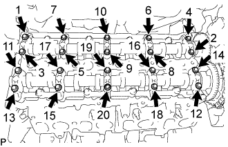
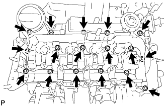
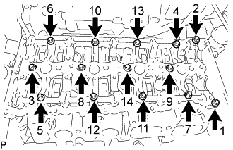
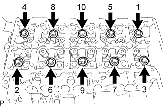
Using an E8 "TORX" socket wrench, uniformly loosen the 20 bolts 180° in several steps in the sequence shown in the illustration.
-
Uniformly loosen the 20 bolts further in several steps in the sequence shown in the illustration and remove the bolts.
-
Remove the 5 intake camshaft bearing caps and 5 exhaust camshaft bearing caps.
Tech Tips
Arrange the removed parts in the correct order.
-
Remove the camshaft and No. 2 camshaft.
-
-
REMOVE CAMSHAFT HOUSING SUB-ASSEMBLY
-
Using an E10 "TORX" socket wrench, remove the 14 bolts and camshaft housing sub-assembly.
-
Remove the 4 gaskets.
-
-
REMOVE NO. 1 VALVE ROCKER ARM SUB-ASSEMBLY
-
Remove the 16 No. 1 valve rocker arm sub-assemblies.
Tech Tips
Arrange the removed parts in the correct order.
-
-
REMOVE VALVE LASH ADJUSTER ASSEMBLY
-
Remove the 16 valve lash adjuster assemblies from the cylinder head sub-assembly.
Tech Tips
Arrange the removed parts in the correct order.
-
-
REMOVE CYLINDER HEAD SUB-ASSEMBLY
-
Using an E10 "TORX" socket wrench, remove the 5 bolts.
-
Using an E18 "TORX" socket wrench, uniformly loosen the 10 cylinder head bolts in several steps in the sequence shown in the illustration.
Note
Do not reuse the cylinder head bolt.
-
Remove the 10 cylinder head bolts and cylinder head sub-assembly.
-
-
REMOVE CYLINDER HEAD GASKET
-
Remove the cylinder head gasket from the cylinder block.
-
-
REMOVE CRANKSHAFT PULLEY
-
Remove the plug from the cylinder block.
-
Set SST (A) to the plug hole of the cylinder block.
SST PZ4TB-04951-26 -
Text in Illustration *a Groove Using SST (B), turn the crankshaft pulley clockwise until SST (A) fits into the groove of the flywheel with damper assembly.
SST PZ4TB-04933-80 -
Using SST (A), hold the flywheel with damper assembly.
-
Using an E10 "TORX" socket wrench, remove the 4 bolts and crankshaft pulley.
-
-
REMOVE TIMING GEAR CASE OR TIMING CHAIN CASE OIL SEAL
-
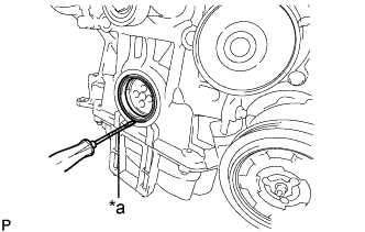
Text in Illustration *a Protective Tape Using a screw driver, pry out the timing gear case or timing chain case oil seal.
Note
Do not damage the oil seal press fit hole, crankshaft or the surface of the timing gear case or timing chain case.
Tech Tips
Tape the screw driver tip before use.
-
-
REMOVE CLUTCH COVER ASSEMBLY
-
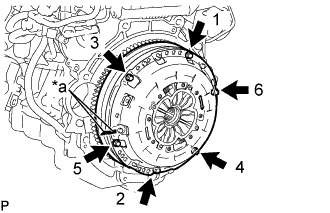
Text in Illustration *a Matchmark Place matchmarks on the clutch cover and flywheel.
-
Loosen each set bolt 180° at a time until the spring tension is released.
Note
Be sure to uniformly loosen the bolts 180° at a time according to the order in the illustration.
-
Remove the set bolts and pull off the clutch cover to remove it.
Note
Do not drop the clutch disc.
-
-
REMOVE CLUTCH DISC ASSEMBLY
Note
Keep the lining part of the clutch disc, the pressure plate, and the surface of the flywheel away from oil and foreign matter.
-
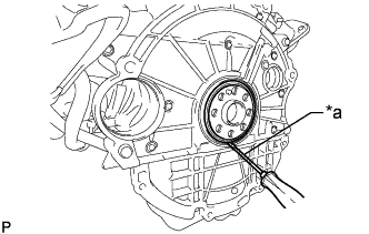
REMOVE FLYWHEEL WITH DAMPER ASSEMBLY
-
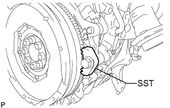
Using SST, fix the flywheel with damper assembly.
SST PZ4TB-04939-38 -
Using SST, remove the 8 bolts and flywheel with damper assembly.
SST PZ4TB-04910-18 -
Remove SST.
-
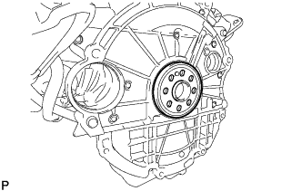
Remove the crankshaft position sensor plate from the crankshaft.
-
-
REMOVE FUEL SUPPLY PUMP ASSEMBLY
-
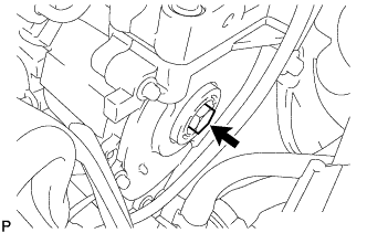
Remove the sealing cap from the timing chain cover plate.
-
Remove the O-ring from the sealing cap.
-
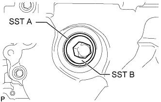
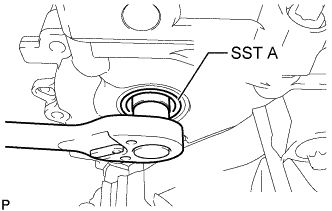
Using SST B, install SST A to position the fuel supply pump assembly. Then remove SST B.
SST PZ4TB-04967-25 Note
SST A remains in the timing chain cover plate until the end of the repair work.
-
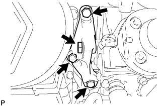
Remove the 4 bolts and fuel supply pump assembly support.
-
Remove the 2 bolts from the fuel supply pump assembly.
-
Text in Illustration *1 Central Bolt Remove the screw connection between the fuel supply pump assembly and injection pump drive gear.
Note
-
SST A remains in the timing chain cover plate.
-
The central bolt is supported on SST A until the fuel supply pump assembly pressed out.
-
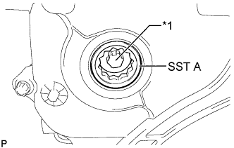
The central bolt remains inside SST A attached to the injection pump drive gear.
-
-
Remove the fuel supply pump assembly from the cylinder block.
-
-
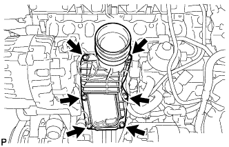
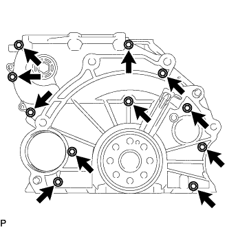
REMOVE OIL PAN SUB-ASSEMBLY
-
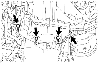
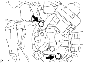
Remove the 4 bolts from the oil pan sub-assembly.
-
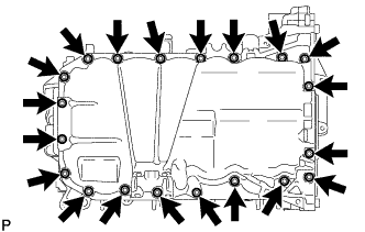
Using an E10 "TORX" socket wrench, remove the 20 bolts from the oil pan sub-assembly.
-
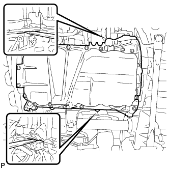
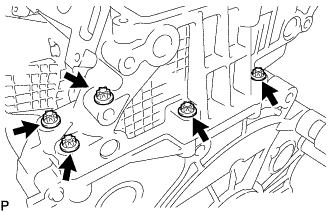
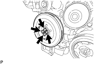
Pry the oil pan sub-assembly at the locations shown in the illustration to remove the oil pan sub-assembly.
Note
Be careful not to damage the contact surfaces of the oil pan sub-assembly and cylinder block.
-
-
REMOVE OIL STRAINER SUB-ASSEMBLY
-
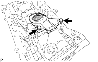
Remove the 2 bolts and oil strainer sub-assembly.
-
-
REMOVE OIL PUMP WITH VACUUM PUMP ASSEMBLY
-
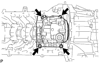
Using an E10 "TORX" socket wrench, remove the 4 bolts from the oil pump with vacuum pump assembly.
-
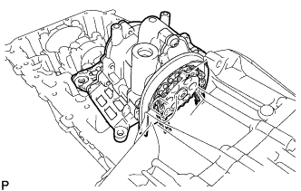
Remove the oil pump drive chain sub-assembly from the oil pump drive shaft gear, and then remove the oil pump with vacuum pump assembly.
Tech Tips
Do not drop the oil pump drive chain sub-assembly into the gap between the rear gear case and cylinder block.
-
Suspend the oil pump drive chain with a string or equivalent.
-
-
REMOVE REAR ENGINE OIL SEAL
-
Text in Illustration *a Protective Tape Using a screw driver, pry out the rear engine oil seal.
Note
Do not damage the rear engine oil seal press fit hole, crankshaft or the surface of the timing chain cover plate.
Tech Tips
Tape the screw driver tip before use.
-
-
REMOVE TIMING CHAIN COVER PLATE
-
Using an E8 "TORX" socket wrench, remove the 11 bolts and timing chain cover plate.
-
-
REMOVE OIL PUMP DRIVE CHAIN SUB-ASSEMBLY
-
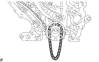
Remove the oil pump drive chain sub-assembly from the crankshaft.
-
-
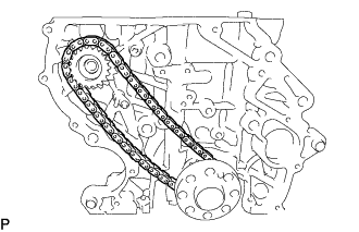
REMOVE NO. 2 CHAIN SUB-ASSEMBLY
-
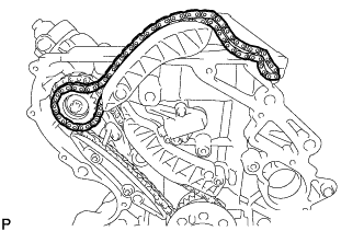
Remove the No. 2 chain sub-assembly from the injection pump drive gear.
-
-
REMOVE NO. 2 TIMING CHAIN TENSION ARM
-
Using a T45 "TORX" socket wrench, remove the bolt and No. 2 timing chain tension arm.
-
-
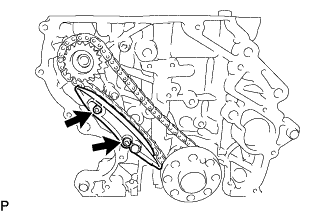
REMOVE NO. 1 CHAIN TENSIONER ASSEMBLY
-
Text in Illustration *a Hexagon Wrench Slowly push the plunger deep into the No. 1 chain tensioner assembly and insert a 3.0 mm hexagon wrench into the No. 1 chain tensioner assembly.
-
Using an E8 "TORX" socket wrench, remove the 2 bolts and No. 1 chain tensioner assembly.
-
-
REMOVE TIMING CHAIN TENSION ARM
-
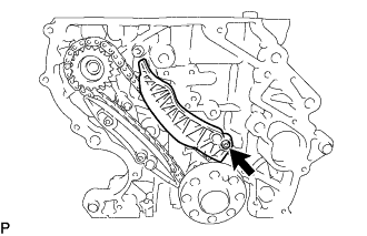
Using a T45 "TORX" socket wrench, remove the bolt and timing chain tension arm.
-
-
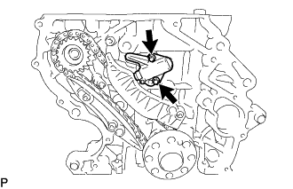
REMOVE TIMING CHAIN GUIDE
-
Using a T45 "TORX" socket wrench, remove the 2 bolts and timing chain guide.
-
-
REMOVE INJECTION PUMP DRIVE GEAR
-
Remove the injection pump drive gear and chain sub-assembly.
-
-
REMOVE NO. 2 OIL NOZZLE SUB-ASSEMBLY
-
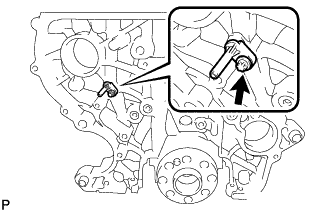
Using an E8 "TORX" socket wrench, remove the bolt and No. 2 oil nozzle sub-assembly.
-