РАСПРЕДВАЛ УСТАНОВКА

Note
-
Always be sure to check the tightening torque.
-
If the pressure lines are leaking after installation, they must be replaced.
-
Do not overtighten the pressure lines.
-
INSPECT VALVE LASH ADJUSTER ASSEMBLY
Note
-
Keep the valve lash adjuster free from dirt and foreign objects.
-
Use only clean engine oil.
-
Place the valve lash adjuster assembly into a container full of new engine oil.
-
Insert SST tip into the valve lash adjuster plunger and use the tip to press down on the check ball inside the plunger.
- SST
- 09276-75010
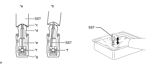
Text in Illustration *a CORRECT *b INCORRECT *c Taper Port *d Plunger *e Lower Pressure Chamber *f Check Ball *g High Pressure Chamber - - -
Squeeze SST and the valve lash adjuster together to move the plunger up and down 5 to 6 times.
-
Check the movement of the plunger and bleed air.
OK Plunger moves up and down. Note
When bleeding high-pressure air from the compression chamber, make sure that the tip of SST is actually pressing the check ball as shown in the illustration. If the check ball is not pressed, air will not bleed.
-
After bleeding air, remove SST. Then quickly and firmly press the plunger repeatedly with your fingers.
OK Plunger can be pressed 3 times. If the plunger can still be compressed after pressing it 3 times, replace the valve lash adjuster assembly with a new one.
-
-
INSTALL VALVE LASH ADJUSTER ASSEMBLY
-
Install the 16 valve lash adjuster assemblies to the cylinder head sub-assembly.
Note
Install the valve lash adjuster assemblies to their original positions.
-
-
INSTALL NO. 1 VALVE ROCKER ARM SUB-ASSEMBLY
-
Install the 16 No. 1 valve rocker arm sub-assemblies.
-
-
INSTALL CAMSHAFT HOUSING SUB-ASSEMBLY
-
Install 4 new gaskets.
-
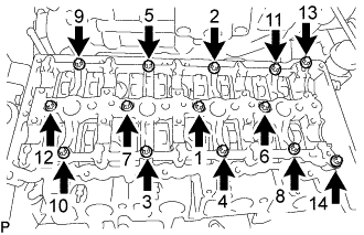
Uniformly tighten the 14 bolts in several steps in the sequence shown in the illustration.
-
Using an E10 "TORX" socket wrench, install camshaft housing sub-assembly with the 14 bolts.
- Torque:
- 13 N*m { 133 kgf*cm, 10 ft.*lbf }
-
-
SET NO. 1 CYLINDER TO TDC/COMPRESSION
-
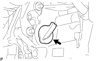
Remove the plug from the cylinder block.
-
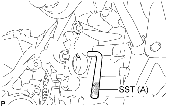
Set SST (A) to the plug hole of the cylinder block.
SST(A) PZ4TB-04951-26 -
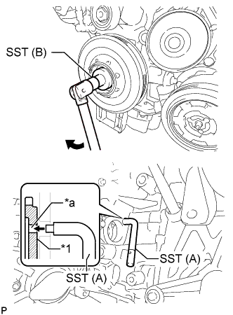
Text in Illustration *1 Flywheel with Damper Assembly *a Groove Using SST (B), turn the crankshaft pulley clockwise until SST(A) fits into the groove of the flywheel with damper assembly.
SST (B) PZ4TB-04933-80 -
Using SST(A), hold the flywheel with damper assembly.
SST (A) PZ4TB-04951-26 -
Remove SST.
-
Install the plug to the cylinder block.
-
-
INSTALL CAMSHAFT AND NO. 2 CAMSHAFT
-
Apply clean engine oil to the cam lobe of each camshaft, journals of the camshaft housing sub-assembly and No. 1 valve rocker arm sub-assemblies.
-
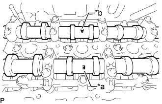
Place the camshaft and No. 2 camshaft on the camshaft housing sub-assembly as shown in the illustration so that mark E and mark A face upward.
Text in Illustration *a Mark E (Intake Side) *b Mark A (Exhaust Side) Note
Before and after setting the camshaft and No. 2 camshaft on the camshaft housing sub-assembly, check that the No. 1 valve rocker arm sub-assembly is firmly set to the valve lash adjuster assembly.
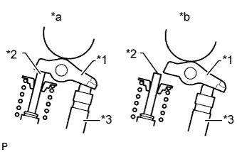
Text in Illustration *1 No. 1 Valve Rocker Arm Sub-assembly *2 Valve Stem *3 Valve Lash Adjuster Assembly *a CORRECT *b INCORRECT -
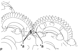
Text in Illustration *a Timing Mark Align the camshaft and No. 2 camshaft timing marks.
-
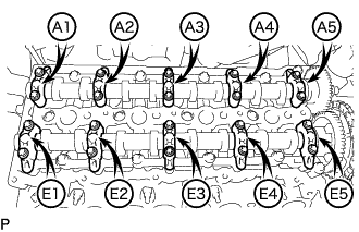
Set the 5 intake camshaft bearing caps and 5 exhaust camshaft bearing caps on the camshaft and No. 2 camshaft as shown in the illustration.
-
Using an E8 "TORX" socket wrench, partially tighten the 20 bolts.
-
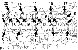
Uniformly tighten the 20 bolts in several steps in the sequence shown in the illustration.
- Torque:
- 10 N*m { 102 kgf*cm, 7 ft.*lbf }
-
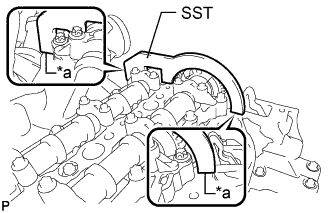
Text in Illustration *a No clearance Using SST, hold the camshaft and No. 2 camshaft.
SST PZ4TB-04961-12 Note
Make sure there is no clearance between SST and the camshaft housing sub-assembly.
-
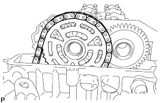
Using an E10 "TORX" socket wrench, temporarily install the camshaft timing sprocket with No. 2 chain sub-assembly to the camshaft with the 3 bolts.
-
Step 1:
Tighten the 3 bolts.
- Torque:
- 10 N*m { 102 kgf*cm, 7 ft.*lbf }
-
Step 2:
Loosen the 3 bolts 90°.
-
-
Using a T45 "TORX" socket wrench, install the No. 2 timing chain guide with the bolt.
- Torque:
- 20 N*m { 204 kgf*cm, 15 ft.*lbf }
-
Using a 24 mm socket wrench, install the No. 2 chain tensioner assembly.
- Torque:
- 70 N*m { 714 kgf*cm, 52 ft.*lbf }
-
Using an E10 "TORX" socket wrench, install the camshaft timing sprocket with the 3 bolts.
- Torque:
- 14 N*m { 143 kgf*cm, 10 ft.*lbf }
-
Remove SST from the camshaft.
-
-
INSTALL NO. 2 ENGINE HANGER
-
Install the No. 2 engine hanger to the cylinder head sub-assembly with the 2 bolts.
Tech Tips
Refer to "SPECIFICATIONS - STANDARD BOLT" for the tightening torque.
-
-
INSTALL NO. 1 EXHAUST MANIFOLD HEAT INSULATOR
-
Install the No. 1 exhaust manifold heat insulator with the 2 bolts.
- Torque:
- 8.0 N*m { 82 kgf*cm, 71 in.*lbf }
-
Attach the 2 clamps and connect the engine wire.
-
-
INSTALL NO. 1 TURBO INSULATOR
-
Install the No. 1 turbo insulator with the 3 bolts and nut.
- Torque:
- 8.0 N*m { 82 kgf*cm, 71 in.*lbf }
-
-
INSTALL CYLINDER HEAD COVER SUB-ASSEMBLY
-
Install 5 new gaskets to the cylinder head cover sub-assembly.
-
Install the cylinder head cover sub-assembly and tighten the 17 bolts.
Tech Tips
Refer to "SPECIFICATIONS - STANDARD BOLT" for the tightening torque.
-
-
INSTALL OIL FILLER CAP SUB-ASSEMBLY
-
INSTALL VACUUM CONTROL VALVE BRACKET
-
Using a T20 "TORX" socket wrench, connect the vacuum control valve bracket with the 3 screws.
-
Attach the air fuel ratio sensor clamp to the vacuum control valve bracket.
-
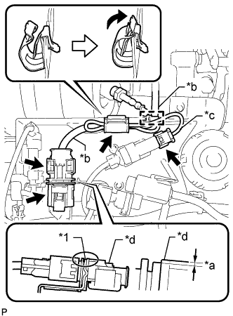
Text in Illustration *1 Vacuum Control Valve Bracket *a 1.5 mm (0.0591 in.) or less *b Air Fuel Ratio Sensor Connector Wire *c Exhaust Gas Temperature Sensor Connector Wire *d Air Fuel Ratio Sensor Connector Move the clamp as shown in the illustration, and secure the air fuel ratio sensor and exhaust gas temperature sensor with the clamp.
Note
The wire harness may become damaged if not installed when the clamp is open.
-
Lower the air fuel ratio sensor connector to the position shown in the illustration.
-
Connect the air fuel ratio sensor connector.
-
Connect the exhaust gas temperature sensor connector.
-
Attach the wire harness clamp.
-
Connect the exhaust gas temperature sensor connector.
-
-
INSTALL INJECTOR ASSEMBLY
Note
-
Before installing the injector assembly, check for carbon, foreign matter, etc. on the seal surfaces of the cylinder head sub-assembly and injector assembly. If there is foreign matter, remove it before installing the injector assembly.
-
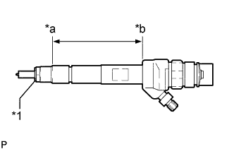
Make sure to replace the copper sealing ring on the injector assembly.
Text in Illustration *1 Copper Sealing Ring *a Point Above the Copper Sealing Ring *b Injector Assembly Slot End -
Before installing the injector assemblies to the injector assembly slots, apply a light coat of highly heat-resistant grease from above the top of the copper sealing ring to the injector assembly slot end.
-
Check the installation position of the high pressure connection.
-
Make sure to read the adjustment values each time new injector assemblies are installed.
Tech Tips
Perform "Inspection After Repairs" after replacing the fuel injector assembly Click here.
-
Install the 4 injector assemblies to the cylinder head cover sub-assembly.
-
Using an E10 "TORX" socket wrench, install the 4 clamping claws to the 4 injector assemblies with the 4 centering rings and 4 bolts.
- Torque:
- 10 N*m { 102 kgf*cm, 7 ft.*lbf }
Note
-
Retighten the clamping claw (cylinder head cover mounting).
-
Make sure the screw centering ring is correctly positioned in order to align the clamping claw.
-
Connect the 4 injector assembly connectors.
-
-
INSTALL NOZZLE LEAKAGE PIPE ASSEMBLY
-
Install 4 new sealing rings to the nozzle leakage pipe assembly.
-
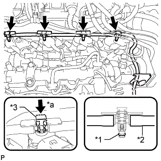
Text in Illustration *1 Sealing Ring *2 Leakage Line *3 Clip *a Push Down Connect the nozzle leakage pipe assembly to the 4 injector assemblies and push down the 4 clips to install the nozzle leakage pipe assembly.
-
Connect the connector and attach the 2 clamps to connect the wire harness.
-
-
INSTALL CAMSHAFT POSITION SENSOR
-
Apply a light coat of engine oil to the O-ring of the camshaft position sensor.
Note
-
When reusing the camshaft position sensor, inspect the O-ring.
-
Make sure that the O-ring is not cracked or jammed when installing the camshaft position sensor.
-
-
Using an E6 "TORX" socket wrench, install the camshaft position sensor with the bolt.
- Torque:
- 3.6 N*m { 37 kgf*cm, 32 in.*lbf }
-
Connect the camshaft position sensor connector.
-
-
INSTALL COMMON RAIL ASSEMBLY
-
Install the common rail assembly to the cylinder head cover sub-assembly.
-
Using an E10 "TORX" socket wrench, install the 2 common rail assembly brackets with the 4 bolts.
Tech Tips
Refer to "SPECIFICATIONS - STANDARD BOLT" for the tightening torque.
-
Connect the fuel return tube.
-
Connect the pressure discharge valve connector.
-
Connect the fuel pressure sensor connector.
-
-
INSTALL INJECTION PIPE SUB-ASSEMBLY
Note
-
If the pressure lines are leaking after installation, they must be replaced.
-
Do not overtighten the pressure lines.
-
Temporarily install the 2 No. 1 injection pipe sub-assemblies and 2 No. 2 injection pipe sub-assemblies at the common rail assembly end by hand.
-
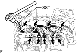
Using a SST, tighten the 4 union nuts at the common rail assembly end of the 2 No. 1 injection pipe sub-assemblies and 2 No. 2 injection pipe sub-assemblies as shown in the illustration.
SST PZ4TB-04959-10 - Torque:
- 24 N*m { 245 kgf*cm, 18 ft.*lbf }
Note
Reset SST in a timely manner to prevent bending of pressure lines.
-
Using SST, tighten the 4 union nuts at the 4 injector assembly ends of the 2 No. 1 injection pipe sub-assemblies and 2 No. 2 injection pipe sub-assemblies.
SST PZ4TB-04959-10 - Torque:
- 24 N*m { 245 kgf*cm, 18 ft.*lbf }
Note
Reset SST in a timely manner to prevent bending of pressure lines.
-
Check all components of the common rail system for tightness.
-
-
INSTALL NO. 3 INJECTION PIPE SUB-ASSEMBLY
Note
-
If the pressure lines are leaking after installation, they must be replaced.
-
Do not overtighten the pressure lines.
-
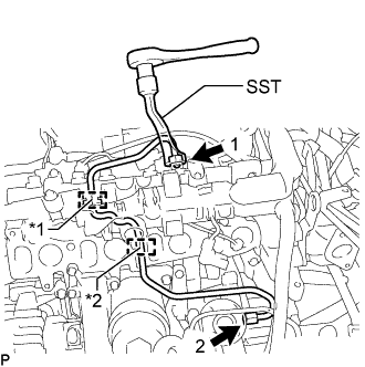
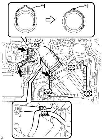
Text in Illustration *1 Rubber Grommet *2 Rubber Mount Install the fuel inlet pipe sub-assembly to the rubber grommet and rubber mount as shown in the illustration.
Note
Install the rubber mount and rubber grommet at the correct positions on the pressure line.
-
Temporarily install the union nut at the fuel supply pump assembly end and common rail assembly end of the fuel inlet pipe sub-assembly by hand.
-
Using SST, tighten the union nut at the fuel supply pump assembly end and common rail assembly end of the fuel inlet pipe sub-assembly as shown in the illustration.
SST PZ4TB-04959-10 - Torque:
- 24 N*m { 245 kgf*cm, 18 ft.*lbf }
Note
Reset SST in a timely manner to prevent bending of pressure lines.
-
-
INSTALL INTAKE MANIFOLD
-
Install a new gasket to the No. 2 EGR pipe sub-assembly.
Tech Tips
Make sure that the claw of the gasket faces the No. 2 EGR pipe sub-assembly.
-
Install 4 new gaskets to the intake manifold.
-
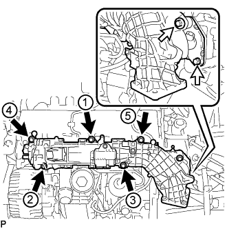
Temporarily install the intake manifold with the 7 bolts.
Text in Illustration 
Bolt A 
Bolt B -
Step 1:
Tighten the 5 bolts labeled A of the intake manifold in the order shown in the illustration.
- Torque:
- 5.0 N*m { 51 kgf*cm, 44 in.*lbf }
-
Step 2:
Tighten the 5 bolts labeled A in the order shown in the illustration again.
- Torque:
- 10 N*m { 102 kgf*cm, 7 ft.*lbf }
-
Step 3:
Tighten the 2 bolts labeled B.
- Torque:
- 8.0 N*m { 82 kgf*cm, 71 in.*lbf }
-
-
INSTALL NO. 1 VACUUM PIPE
-
Install a new O-ring to the No. 1 vacuum pipe.
-
Using an E7 "TORX" socket wrench, install the No. 1 vacuum pipe with the bolt to the cylinder block sub-assembly.
- Torque:
- 8.0 N*m { 82 kgf*cm, 71 in.*lbf }
-
Connect the vacuum hose.
-
-
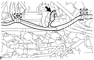
CONNECT NO. 2 VACUUM HOSE ASSEMBLY
-
Connect the No. 2 vacuum hose assembly to the No. 1 vacuum pipe.
-
Check that there is no damage or contamination in the connected part of the No. 1 vacuum pipe.
-
Line up the No. 1 vacuum pipe and No. 2 vacuum hose assembly connector and push them together until a "click" sound is heard. If the connection is tight, apply a small amount of clean engine oil to the tip of the No. 1 vacuum pipe.
-
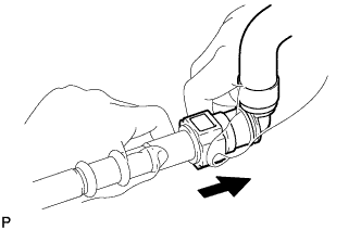
After connecting the No. 1 vacuum pipe and No. 2 vacuum hose assembly connector, check that the No. 1 vacuum pipe and No. 2 vacuum hose assembly connector are securely connected by pulling on them.
Text in Illustration Pull
-
-
-
INSTALL ENGINE OIL LEVEL DIPSTICK GUIDE
-
Install a new O-ring to the engine oil level dipstick guide.
-
Using a T25 "TORX" socket wrench, install the engine oil level dipstick guide with the bolt.
Tech Tips
Refer to "SPECIFICATIONS - STANDARD BOLT" for the tightening torque.
-
Attach the clamp and connect the fuel feed pipe sub-assembly to the engine oil level dipstick guide.
-
Install the engine oil level dipstick.
-
-
CONNECT ENGINE WIRE
-
Using a T25 "TORX" socket wrench, connect the engine wire and install the screw.
Tech Tips
Refer to "SPECIFICATIONS - STANDARD BOLT" for the tightening torque.
-
Attach the 2 clamps.
-
Connect the 2 glow plug controller assembly connectors.
-
Connect the turbo pressure sensor assembly connector.
-
Connect the camshaft position sensor connector.
-
Connect the generator assembly connector.
-
Connect the engine coolant temperature sensor connector.
-
Connect the fuel pressure sensor connector.
-
Connect the swirl control valve connector.
-
Attach the 6 clamps and connect the fuel quantity control valve connector.
-
Connect the EGR gas temperature sensor connector.
-
Attach the 2 clamps and connect the glow plug controller assembly harness connector.
-
-
INSTALL AIR CLEANER CASE SUB-ASSEMBLY
-
Install the air cleaner case sub-assembly with the 3 bolts.
- Torque:
- 7.0 N*m { 71 kgf*cm, 62 in.*lbf }
-
-
INSTALL AIR CLEANER FILTER ELEMENT SUB-ASSEMBLY
-
INSTALL AIR CLEANER CAP SUB-ASSEMBLY WITH AIR CLEANER HOSE ASSEMBLY
-
Text in Illustration *1 Retainer Connect the air cleaner hose assembly to the turbocharger sub-assembly and lock the retainer as shown in the illustration.
-
Attach the 2 clamps to install the air cleaner cap sub-assembly.
-
Connect the ventilation hose to the cylinder head cover sub-assembly.
-
Attach the clamp and connect the No. 2 fuel hose to the air cleaner hose assembly.
-
Attach the clamp and connect the No. 1 fuel hose to the air cleaner hose assembly.
-
Attach the clamp and connect the vacuum hose to the air cleaner hose assembly.
-
Attach the clamp and connect the mass air flow meter sub-assembly connector.
-
-
INSTALL ENGINE COVER
-
INSTALL DIESEL THROTTLE BODY ASSEMBLY
-
INSTALL RADIATOR ASSEMBLY
-
CONNECT CABLE TO NEGATIVE BATTERY TERMINAL
Note
When disconnecting the cable, some systems need to be initialized after the cable is reconnected Click here.
-
INSPECT FOR FUEL LEAK
-
Check fuel pump operation.
-
Connect the GTS to the DLC3.
-
Turn the ignition switch to ON and turn the GTS on.
Note
Do not start the engine.
-
Enter the following menus: Powertrain / Engine and ECT / Active Test / Actuator Test of FPC (EU5).
-
Check for pressure in the fuel inlet tube from the fuel line. Check that sounds of fuel flowing from the fuel tank can be heard. If no sounds can be heard, check the No. 1 integration relay, fuel suction with pump and gauge tube assembly, ECM and wiring connectors.
-
-
Inspect for fuel leaks.
-
Check that there are no fuel leaks from the fuel system after doing any maintenance or repairs. If there is a fuel leak, repair or replace parts as necessary.
-
-
Turn the ignition switch off.
-
Disconnect the GTS from the DLC3.
-
-
INSPECT FOR OIL LEAK
-
Start the engine. Make sure that there are no oil leaks from the areas that were worked on.
-