БЛОК ДВИГАТЕЛЯ РАЗБОРКА

Note
-
When replacing the injectors (including shuffling the injectors between the cylinders), common rail, intake manifold or cylinder head, it is necessary to replace the injection pipes with new ones.
-
When replacing the fuel supply pump, common rail, intake manifold or cylinder head, it is necessary to replace the fuel inlet pipe with a new one.
-
REMOVE NO. 2 NOZZLE LEAKAGE PIPE
-
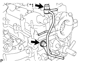
Text in Illustration *1 Check Valve Remove the check valve and gasket.
-
Remove the bolt and No. 2 nozzle leakage pipe.
-
-
REMOVE NO. 1 NOZZLE LEAKAGE PIPE
-
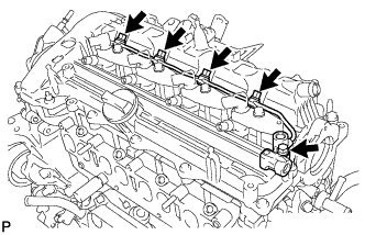
Remove the 4 union bolts and 4 gaskets.
-
Remove the bolt and No. 1 nozzle leakage pipe.
-
-
REMOVE NO. 1 NOZZLE HOLDER CLAMP
-
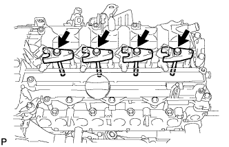
Remove the 4 bolts, 4 washers and 4 nozzle holder clamps.
-
-
REMOVE INJECTOR ASSEMBLY
-
Remove the 4 injectors and 4 injection nozzle seats from the cylinder head.
-
Remove the O-ring from each injector.
Note
When removing the injector assembly, store the injectors in the correct order so that they can be returned to their original locations when reassembling.
-
-
REMOVE CAMSHAFT POSITION SENSOR
-
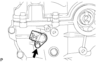
Remove the bolt and sensor.
-
-
REMOVE CRANKSHAFT POSITION SENSOR
-
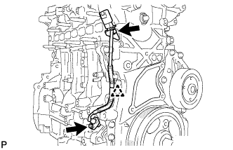
Remove the clip and disconnect the sensor harness.
-
Remove the 2 bolts and crankshaft position sensor.
-
-
REMOVE ENGINE COOLANT TEMPERATURE SENSOR
-
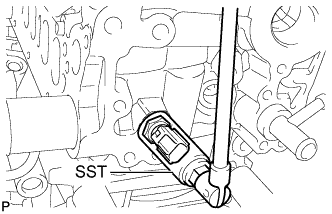
Using SST, remove the sensor and gasket.
- SST
- 09817-33190
-
-
REMOVE WATER PUMP ASSEMBLY
-
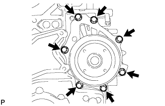
Remove the 7 bolts, water pump and gasket.
-
-
REMOVE ENGINE OIL PRESSURE SWITCH ASSEMBLY
-
Disconnect the engine oil pressure switch connector.
-
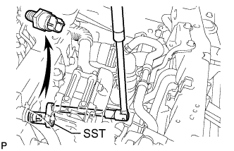
Using SST, remove the engine oil pressure switch.
- SST
- 09224-00010
-
-
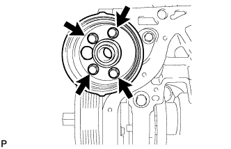
REMOVE OIL COOLER ASSEMBLY
-
Remove the 5 bolts and oil cooler.
-
Remove the 3 O-rings from the oil cooler bracket.
-
-
REMOVE NO. 1 OIL COOLER BRACKET
-
Remove the 6 bolts, nut and No. 1 oil cooler bracket.
Text in Illustration 
Nut -
Remove the 3 O-rings from the No. 1 oil cooler bracket.
-
-
REMOVE ENGINE OIL LEVEL SENSOR
-
Remove the 4 bolts and sensor.
-
-
REMOVE WATER INLET HOUSING
-
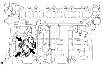
Remove the 3 nuts, water inlet housing and gasket.
-
-
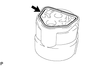
REMOVE OIL FILLER CAP SUB-ASSEMBLY
-
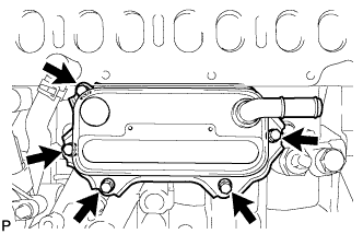
REMOVE CYLINDER HEAD COVER SUB-ASSEMBLY
-
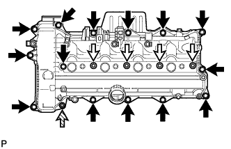
Remove the 4 nozzle holder clamp seats, 14 bolts, nut and cylinder head cover.
Text in Illustration 
Bolt Nozzle Holder Clamp Seat 
Nut -
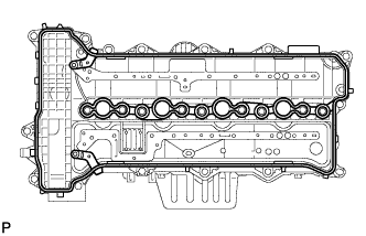
Remove the cylinder head cover gasket from the cylinder head cover.
-
-
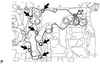
REMOVE NO. 2 OIL PAN SUB-ASSEMBLY
-
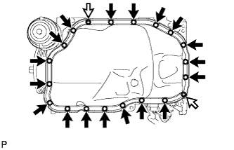
Remove the 18 bolts and 2 nuts.
Text in Illustration Nut -
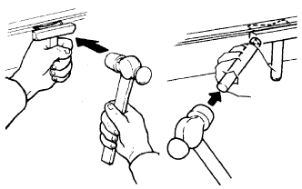
Insert the blade of an oil pan seal cutter between the oil pan and cylinder block, cut through the applied sealer and remove the oil pan.
Note
-
Do not use the oil pan seal cutter for the area between the oil pan and timing chain cover.
-
Be careful not to damage the contact surfaces of the oil pan.
-
-
-
REMOVE OIL FILTER ELEMENT
-
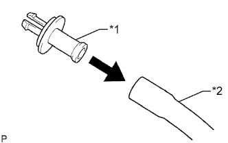
Text in Illustration *1 Oil filter drain pipe *2 Hose Connect a hose with an inside diameter of 15 mm (0.591 in.) to the oil filter drain pipe.
-
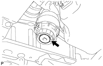
Remove the oil filter drain plug.
-
Remove the O-ring from the oil filter drain plug and install it to an oil filter drain pipe.
-
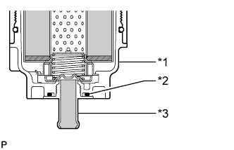
Text in Illustration *1 Oil Filter Cap *2 O-Ring *3 Oil Filter Drain Pipe Install the oil filter drain pipe to the oil filter cap and drain the engine oil.
-
Remove the oil filter drain pipe.
-
Apply a light coat of engine oil to a new O-ring and install it to the oil filter drain plug.
-
Install the oil filter drain plug to the oil filter cap.
- Torque:
- 13 N*m { 127 kgf*cm, 9 ft.*lbf }
-
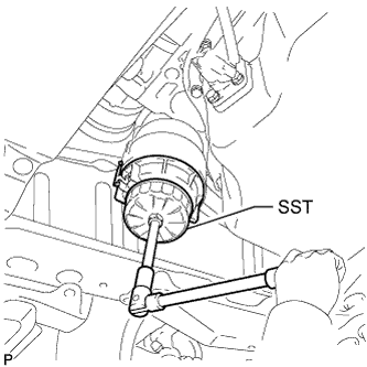
Using SST, remove the oil filter cap.
- SST
- 09228-06501
-
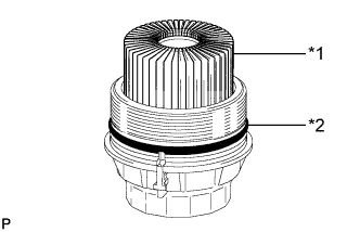
Text in Illustration *1 Oil Filter Element *2 O-Ring Remove the oil filter element and O-ring from the oil filter cap.
Note
Be sure to remove the cap O-ring by hand without using any tools to prevent damage to the cap O-ring groove.
-
-
REMOVE OIL FILTER BRACKET
-
Remove the 4 bolts and oil filter bracket.
-
Remove the gasket from the oil filter bracket.
-
-
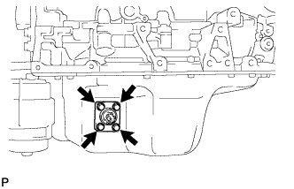
REMOVE OIL STRAINER SUB-ASSEMBLY
-
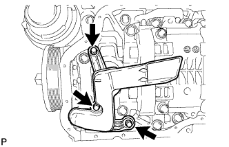
Remove the 3 bolts and oil strainer.
-
Remove the O-ring from the oil strainer.
-
-
REMOVE CRANKSHAFT PULLEY
-
Set the No. 1 piston to TDC/compression.
-
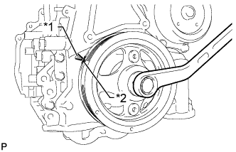
Text in Illustration *1 Timing Pointer *2 Timing Mark Turn the crankshaft pulley clockwise to align the timing mark on the pulley with the timing pointer of the timing chain cover.
-
-
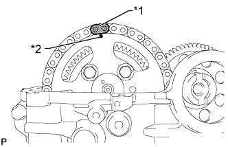
Text in Illustration *1 Matchmark *2 Timing Mark Make sure that the timing mark of the camshaft timing sprocket is at the top.
Tech Tips
If the timing mark is not at the top, turn the crankshaft pulley 1 revolution so that the timing mark is at the top (set the No. 1 piston to TDC/compression).
-
Put a matchmark on the timing chain plate that is aligned with the timing mark of the camshaft timing sprocket.
Tech Tips
The timing chain has 2 yellow-colored plates. If either of them is aligned with the timing mark of the camshaft timing sprocket, this step can be omitted.
-
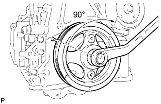
Turn the crankshaft by approximately 90° in the direction of engine revolution from the point where the No. 1 piston is set to TDC/compression so that the lifted valve and piston do not contact each other when removing the camshaft.
-
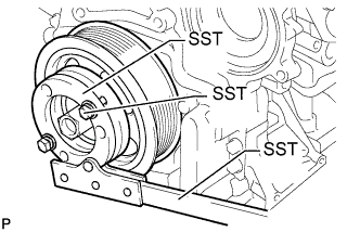
Using SST, loosen the pulley bolt.
- SST
- 09213-58014 ( 91551-80840 )
- 09330-00021
-
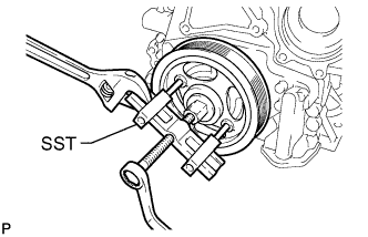
Using SST, remove the pulley bolt and crankshaft pulley.
- SST
- 09950-50013 ( 09951-05010, 09952-05010, 09953-05020, 09954-05021 )
-
-
REMOVE TIMING CHAIN COVER SUB-ASSEMBLY
-
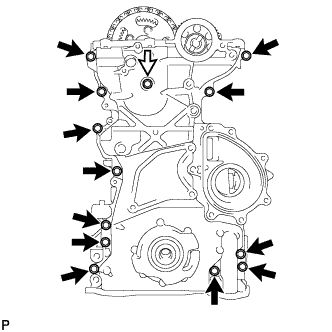
Remove the 13 bolts and seal washer.
Text in Illustration Bolt and Seal Washer -
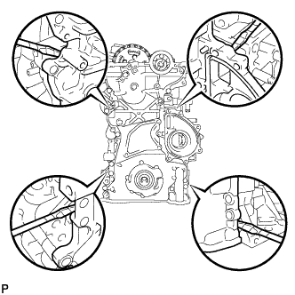
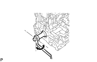
Remove the timing chain cover by prying between the timing chain cover and cylinder head, camshaft housing, cylinder block and stiffening crankcase with a screwdriver as shown in the illustration.
Note
Be careful not to damage the contact surfaces of the cylinder head, camshaft housing, cylinder block, stiffening crankcase and chain cover.
Tech Tips
Tape the screwdriver tip before use.
-
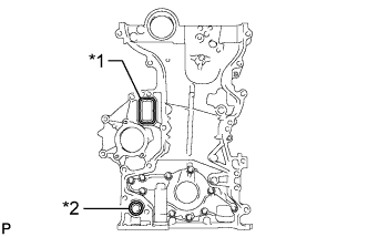
Text in Illustration *1 Gasket *2 O-Ring Remove the gasket and O-ring from the timing chain cover.
-
-
REMOVE FRONT CRANKSHAFT OIL SEAL
-
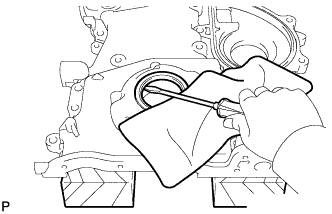
Place the timing chain cover on wooden blocks.
-
Using a screwdriver, pry out the oil seal.
Note
Do not damage the surface of the oil seal press fit hole.
Tech Tips
Tape the screwdriver tip before use.
-
-
REMOVE NO. 1 CHAIN TENSIONER ASSEMBLY
-
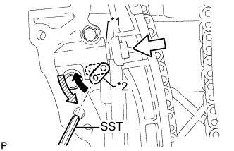
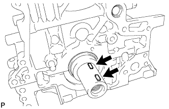
Text in Illustration *1 Plunger *2 Stopper Plate Move the stopper plate upward to release the lock, and push the plunger deep into the No. 1 chain tensioner.
-
Move the stopper plate downward to set the lock, and insert SST into the stopper plate hole.
- SST
- 09240-00020 ( 09242-00200 )
-
Remove the 2 bolts and No. 1 chain tensioner.
-
-
REMOVE CHAIN TENSIONER SLIPPER
-
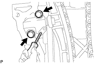
REMOVE NO. 1 CHAIN VIBRATION DAMPER
-
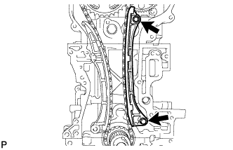
Remove the 2 bolts and No. 1 chain vibration damper.
-
-
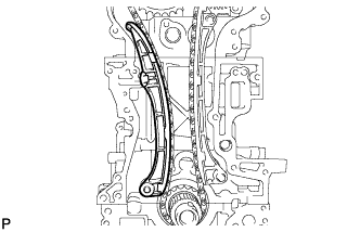
REMOVE CAMSHAFT TIMING SPROCKET
-
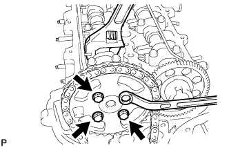
Remove the 4 bolts from the sprocket while holding the hexagonal portion of the No. 2 camshaft with a wrench.
-
Remove the camshaft timing sprocket and chain.
-
-
REMOVE OIL PUMP DRIVE GEAR
-
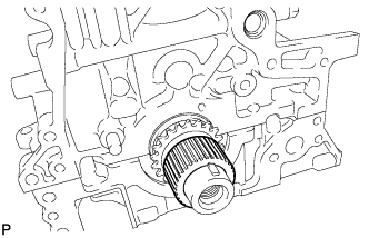
Remove the oil pump drive gear from the crankshaft.
-
-
REMOVE CRANKSHAFT TIMING SPROCKET
-
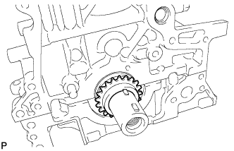
Remove the crankshaft timing sprocket.
-
-
REMOVE KEY
-
Remove the 2 keys from the crankshaft.
-
-
REMOVE CAMSHAFT
-
Using the crankshaft pulley bolt, set the No. 1 cylinder to 90° BTDC/compression.
-
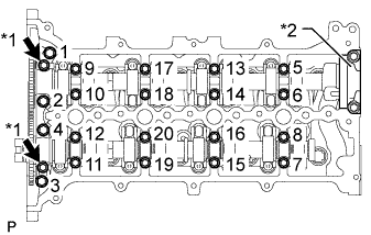
Text in Illustration *1 Oil Pipe Seat *2 No. 4 Bearing Cap Remove the 2 oil pipe seats.
-
Uniformly loosen the 20 bolts in several steps in the sequence shown in the illustration and remove the bolts.
-
Remove the 8 No. 3 bearing caps and No. 1 bearing cap.
Tech Tips
Do not remove the No. 4 bearing cap.
-
Remove the camshaft and No. 2 camshaft.
-
Remove the No. 2 camshaft bearing cap.
-
-
REMOVE NO. 1 VALVE ROCKER ARM SUB-ASSEMBLY
-
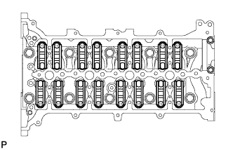
Remove the 16 No. 1 valve rocker arms.
-
-
REMOVE VALVE LASH ADJUSTER ASSEMBLY
-
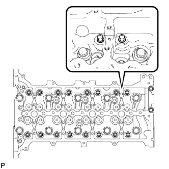
Remove the 16 valve lash adjusters from the cylinder head.
Tech Tips
Arrange the removed parts in the correct order.
-
-
REMOVE CYLINDER HEAD SUB-ASSEMBLY
-
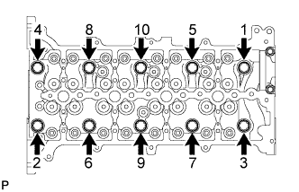
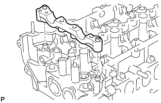
Uniformly loosen the 10 cylinder head bolts in several steps, in the sequence shown in the illustration. Remove the 10 cylinder head bolts and 10 plate washers.
Note
-
Do not drop the washers into the cylinder head.
-
Head warpage or cracking could result from removing bolts in the incorrect order.
-
-
-
REMOVE CYLINDER HEAD GASKET
-
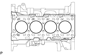
Remove the cylinder head gasket.
-
-
REMOVE REAR CRANKSHAFT OIL SEAL
-
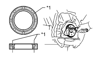
Text in Illustration *1 Cut Position Using a knife, cut off the lip of the oil seal.
-
Using a screwdriver, pry out the oil seal.
Note
Be careful not to damage the crankshaft.
-
-
REMOVE OIL BAFFLE PLATE
-
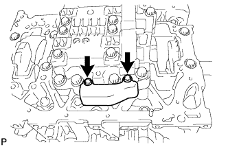
Remove the 2 bolts and oil baffle plate.
-
-
REMOVE ENGINE BALANCER ASSEMBLY
-
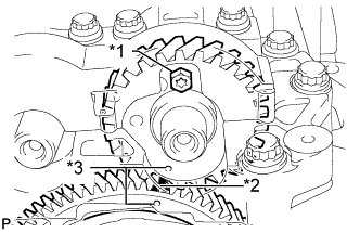
Text in Illustration *1 Service Bolt *2 Matchmark *3 Align Align the timing marks (1 dot mark each) of the drive and driven gears by turning the crankshaft with a wrench.
-
Put matchmarks on the drive gear and driven gear.
-
Install a service bolt.
Recommended Service Bolt Item Specified Condition Thread diameter 6 mm (0.236 in.) Thread pitch 1 mm (0.0394 in.) Bolt length 16 to 18 mm (0.630 to 0.709 in.) - Torque:
- 1.5 N*m { 15 kgf*cm, 13 in.*lbf }
Tech Tips
When removing the balancer, make sure that the torsional spring force of the sub gear has been eliminated by the installation of the service bolt.
-
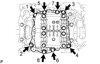
Uniformly loosen the 8 bolts in several steps, in the sequence shown in the illustration.
-
Remove the engine balancer.
-
-
REMOVE CYLINDER BLOCK DRAIN COCK PLUG
-
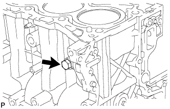
Remove the cylinder block drain cock plug from the cylinder block.
-