БЛОК ЦИЛИНДРОВ РАЗБОРКА
-
REMOVE PISTON SUB-ASSEMBLY WITH CONNECTING ROD
-
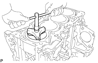
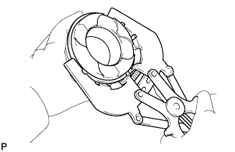
Using a ridge reamer, remove all the carbon from the top of the cylinder.
-
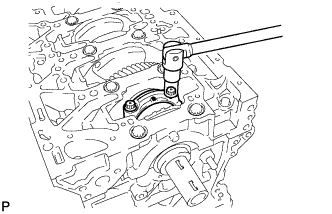
Remove the 2 connecting rod bolts.
-
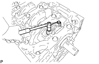
Remove the connecting rod cap with bearing.
-
Push out the piston and connecting rod with bearing through the top of the cylinder block to remove them.
Tech Tips
Arrange the piston and connecting rod assemblies in the correct order.
-
-
REMOVE CONNECTING ROD BEARING
-
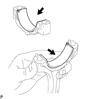
Remove the connecting rod and connecting rod cap bearings.
Tech Tips
Arrange the removed parts in the correct order.
-
-
REMOVE PISTON RING SET
Tech Tips
Arrange the piston rings in the correct order.
-
Using a piston ring expander, remove the No. 1 and No. 2 compression rings.
-
Using a piston ring expander, remove the oil ring rail.
-
Remove the oil ring expander by hand.
-
-
REMOVE PISTON WITH PIN SUB-ASSEMBLY
-
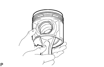
Check the fitting condition between the piston and piston pin by trying to move the piston back and forth on the piston pin.
If any movement is felt, replace the piston and pin as a set.
-
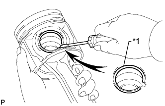
Text in Illustration *1 Snap Ring Using a screwdriver, pry out the 2 snap rings.
-
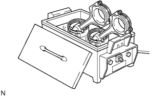
Gradually heat the piston to 80 to 90°C (176 to 194°F).
-
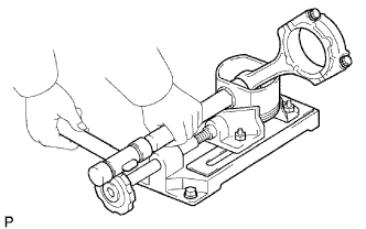
Using a brass bar and plastic-faced hammer, lightly tap out the piston pin and remove the connecting rod.
Tech Tips
-
The piston and pin are a matched set.
-
Arrange the pistons, pins, rings, connecting rods and bearings in the correct order.
-
-
-
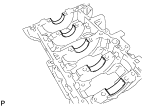
REMOVE CRANKSHAFT
-
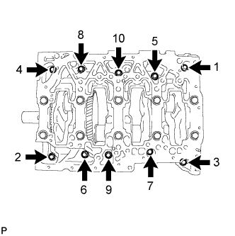
Uniformly loosen and remove the 10 bolts in several steps, in the sequence shown in the illustration.
-
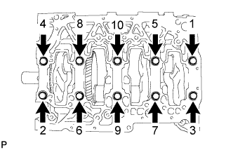
Uniformly loosen and remove the 10 bearing cap bolts in several steps, in the sequence shown in the illustration.
-
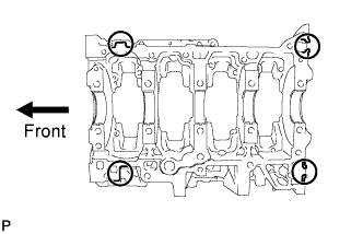
Remove the crankshaft bearing cap by prying between the crankshaft bearing cap and cylinder block with a screwdriver.
Note
Do not damage the contact surfaces of the cylinder block and crankshaft bearing cap.
Tech Tips
-
Keep the lower bearings and crankshaft bearing cap together.
-
Arrange the thrust washers in the correct order.
-
Keep the upper crankshaft bearings and upper crankshaft thrust washers together with the cylinder block.
-
Tape the screwdriver tip before use.
-
-
Remove the crankshaft.
-
-
REMOVE UPPER CRANKSHAFT THRUST WASHER
-
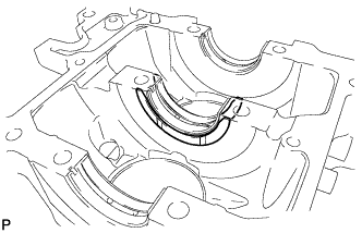
Remove the 2 upper crankshaft thrust washers from the cylinder block.
Tech Tips
Arrange the thrust washers in the correct order.
-
-
REMOVE CRANKSHAFT BEARING
Tech Tips
-
Keep the upper and lower crankshaft bearing and crankshaft bearing cap as a set.
-
Arrange the crankshaft bearing cap and bearings in the correct order.
-
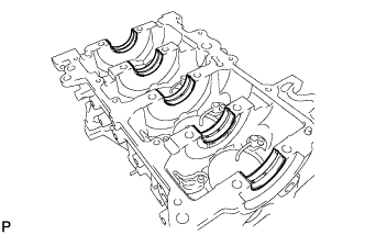
Remove the 5 upper crankshaft bearings.
-
Remove the 5 lower crankshaft bearings.
-
-
REMOVE NO. 1 CRANKSHAFT POSITION SENSOR PLATE
-
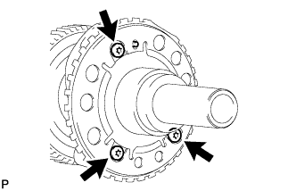
Using a T30 "TORX" socket wrench, remove the 3 bolts and sensor plate.
-
-
REMOVE NO. 1 OIL NOZZLE SUB-ASSEMBLY
-
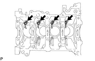
Using a 5 mm hexagon wrench, remove the 4 bolts and 4 oil nozzles.
-
-
REMOVE OIL REFLECTOR PLATE
-
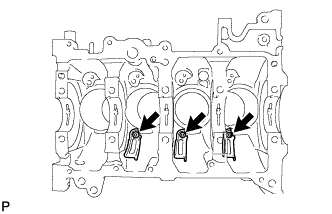
Using a 5 mm hexagon wrench, remove the 3 bolts and 3 oil reflector plates.
-