БЛОК ДВИГАТЕЛЯ УСТАНОВКА

Note
-
When replacing the injectors (including shuffling the injectors between the cylinders), common rail, intake manifold or cylinder head, it is necessary to replace the injection pipes with new ones.
-
When replacing the fuel supply pump, common rail, intake manifold or cylinder head, it is necessary to replace the fuel inlet pipe with a new one.
-
INSTALL DRIVE SHAFT BEARING BRACKET
-
Install the drive shaft bearing bracket with the 3 bolts.
- Torque:
- 64 N*m { 650 kgf*cm, 47 ft.*lbf }
-
-
INSTALL TURBOCHARGER SUB-ASSEMBLY
-
for CCo: Click here
-
for DPF: Click here
-
-
INSTALL EGR COOLER WITH PIPE ASSEMBLY
-
Install a new O-ring to the EGR cooler with pipe.
-
Install a new gasket to the EGR cooler and a new gasket to the No. 1 EGR pipe.
Tech Tips
Make sure the claws of the gasket face the EGR cooler and No. 1 EGR pipe sub-assembly.
-
Temporarily install the EGR cooler with pipe with the 6 bolts and 2 nuts labeled A, B and C.
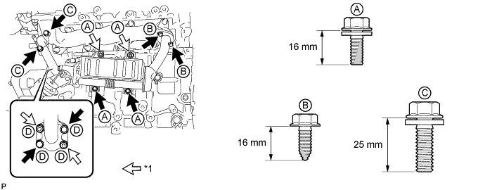
Text in Illustration *1 Nut - - Standard Bolt Item Length Bolt A 16 mm (0.630 in.) Bolt B 16 mm (0.630 in.) Bolt C 25 mm (0.984 in.) -
Tighten the 2 bolts and 2 nuts labeled A shown in the illustration.
- Torque:
- 10 N*m { 102 kgf*cm, 7 ft.*lbf }
-
Tighten the 2 bolts labeled B shown in the illustration.
- Torque:
- 16 N*m { 163 kgf*cm, 12 ft.*lbf }
-
Tighten the 2 bolts labeled C shown in the illustration.
- Torque:
- 24 N*m { 245 kgf*cm, 18 ft.*lbf }
-
Tighten the 2 bolts and 2 nuts labeled D shown in the illustration.
- Torque:
- 21 N*m { 214 kgf*cm, 15 ft.*lbf }
-
Connect the vacuum hose.
-
-
INSTALL NO. 2 WATER BY-PASS HOSE
-
for CCo:
Install the No. 2 water by-pass hose to the EGR cooler and No. 5 water by-pass hose, and slide the 2 clamps to secure it.
-
for DPF:
Install the No. 2 water by-pass hose to the EGR cooler and turbo oil outlet pipe, and slide the 2 clamps to secure it.
-
-
INSTALL EXHAUST MANIFOLD CONVERTER SUB-ASSEMBLY (for CCo)
-
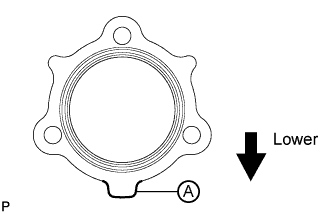
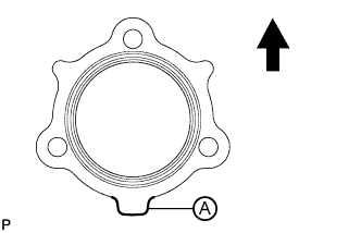
Install a new gasket to the turbocharger.
Tech Tips
Make sure that the part labeled A is facing downwards as shown in the illustration.
-
Temporarily install the exhaust manifold converter with 3 new nuts.
-
Temporarily install the No. 2 exhaust manifold stay with the 2 bolts and nut.
-
Temporarily install the No. 2 manifold stay with the 3 bolts.
-
Temporarily install the manifold stay with the bolt and nut.
-
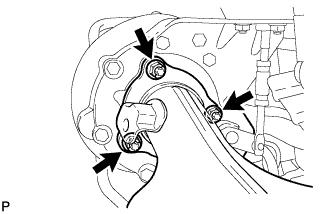
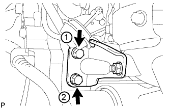
Tighten the 2 bolts of the No. 2 exhaust manifold stay in the order shown in the illustration.
- Torque:
- 56 N*m { 571 kgf*cm, 41 ft.*lbf }
-
Tighten the 3 nuts of the exhaust manifold converter.
- Torque:
- 25 N*m { 255 kgf*cm, 18 ft.*lbf }
Note
Tighten the nuts while pressing the exhaust manifold converter against the engine.
-
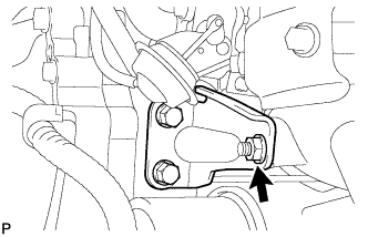
Tighten the nut of the No. 2 exhaust manifold stay.
- Torque:
- 56 N*m { 571 kgf*cm, 41 ft.*lbf }
-
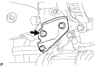
Tighten the bolt of the No. 2 manifold stay shown in the illustration.
- Torque:
- 56 N*m { 571 kgf*cm, 41 ft.*lbf }
Note
Tighten the bolt while pressing the No. 2 manifold stay against the exhaust manifold converter and cylinder block.
-
Tighten the 2 bolts of the No. 2 manifold stay shown in the illustration.
- Torque:
- 56 N*m { 571 kgf*cm, 41 ft.*lbf }
-
Tighten the bolt of the manifold stay.
- Torque:
- 25 N*m { 255 kgf*cm, 18 ft.*lbf }
Note
Tighten the bolt while pressing the manifold stay against the exhaust manifold converter and cylinder block.
-
Tighten the nut of the manifold stay.
- Torque:
- 25 N*m { 255 kgf*cm, 18 ft.*lbf }
-
-
INSTALL EXHAUST MANIFOLD CONVERTER SUB-ASSEMBLY (for DPF)
-
Install a new gasket to the turbocharger sub-assembly.
Text in Illustration 
Top Tech Tips
Make sure that the part labeled A is facing downwards as shown in the illustration.
-
Temporarily install the exhaust manifold converter sub-assembly with 3 new nuts.
-
Temporarily install the No. 2 exhaust manifold stay with the 2 bolts and nut.
-
Temporarily install the No. 2 manifold stay with the 3 bolts.
-
Temporarily install the manifold stay with the bolt and nut.
-
Tighten the 2 bolts of the No. 2 exhaust manifold stay in the order shown in the illustration.
- Torque:
- 56 N*m { 571 kgf*cm, 41 ft.*lbf }
-
Tighten the 3 nuts of the exhaust manifold converter sub-assembly.
- Torque:
- 25 N*m { 255 kgf*cm, 18 ft.*lbf }
Note
Tighten the nuts while pressing the exhaust manifold converter sub-assembly against the engine.
-
Tighten the nut of the No. 2 exhaust manifold stay.
- Torque:
- 56 N*m { 571 kgf*cm, 41 ft.*lbf }
-
Tighten the bolt of the No. 2 manifold stay shown in the illustration.
- Torque:
- 56 N*m { 571 kgf*cm, 41 ft.*lbf }
Note
Tighten the bolt while pressing the No. 2 manifold stay against the exhaust manifold converter sub-assembly and cylinder block.
-
Tighten the 2 bolts of the No. 2 manifold stay shown in the illustration.
- Torque:
- 56 N*m { 571 kgf*cm, 41 ft.*lbf }
-
Tighten the bolt of the manifold stay.
- Torque:
- 25 N*m { 255 kgf*cm, 18 ft.*lbf }
Note
Tighten the bolt while pressing the manifold stay against the exhaust manifold converter sub-assembly and cylinder block.
-
Tighten the nut of the manifold stay.
- Torque:
- 25 N*m { 255 kgf*cm, 18 ft.*lbf }
-
Connect the 2 connectors.
-
-
INSTALL NO. 1 MANIFOLD CONVERTER INSULATOR (for CCo)
-
Install the No. 1 manifold converter insulator with the 4 bolts.
- Torque:
- 29 N*m { 291 kgf*cm, 21 ft.*lbf }
-
-
INSTALL MANIFOLD CONVERTER INSULATOR SUB-ASSEMBLY (for DPF)
-
Install the manifold converter insulator sub-assembly with the bolt.
- Torque:
- 29 N*m { 291 kgf*cm, 21 ft.*lbf }
Note
Make sure that the ceramic wool inside the manifold converter insulator sub-assembly does not fall out and is not bent.
-
-
INSTALL NO. 4 MANIFOLD CONVERTER INSULATOR (for DPF)
-
Install the No. 4 manifold converter insulator with the 4 bolts.
- Torque:
- 29 N*m { 291 kgf*cm, 21 ft.*lbf }
-
-
INSTALL WIRE HARNESS CLAMP BRACKET (for DPF)
-
Install the No. 1 wiring harness clamp bracket with the bolt.
- Torque:
- 9.0 N*m { 92 kgf*cm, 80 in.*lbf }
-
-
INSTALL VACUUM TRANSMITTING HOSE ASSEMBLY
-
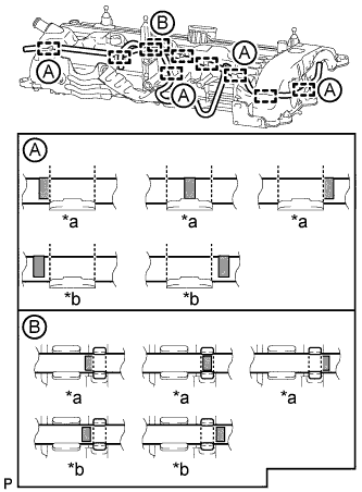
Text in Illustration *a CORRECT *b INCORRECT 
Paint Mark for CCo:
Attach the 10 clamps to install the 2 vacuum transmitting hoses.
Tech Tips
-
Make sure that the paint marks of the vacuum transmitting hoses at the locations labeled A in the illustration are aligned as shown in the illustration. Any of the "CORRECT" alignments are acceptable for each location.
-
Make sure that the paint marks of the vacuum transmitting hoses at the locations labeled B in the illustration are aligned as shown in the illustration. Any of the "CORRECT" alignments are acceptable for each location.
-
-
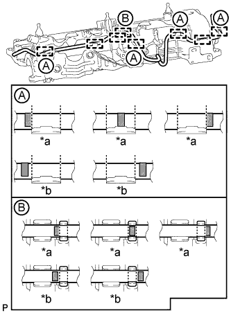
Text in Illustration *a CORRECT *b INCORRECT Paint Mark for DPF:
Attach the 8 clamps to install the 2 vacuum transmitting hoses.
Tech Tips
-
Make sure that the paint marks of the vacuum transmitting hoses at the locations labeled A in the illustration are aligned as shown in the illustration. Any of the "CORRECT" alignments are acceptable for each location.
-
Make sure that the paint marks of the vacuum transmitting hoses at the locations labeled B in the illustration are aligned as shown in the illustration. Any of the "CORRECT" alignments are acceptable for each location.
-
-
-
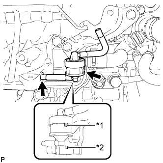
INSTALL NO. 1 VACUUM SWITCHING VALVE ASSEMBLY
-
Using a 4 mm hexagon socket wrench, install the VSV with the 2 bolts.
- Torque:
- 5.0 N*m { 51 kgf*cm, 44 in.*lbf }
-
Connect the 2 vacuum hoses.
-
Connect the VSV connector.
-
-
INSTALL VACUUM REGULATING VALVE ASSEMBLY (for CCo)
-
Install the vacuum regulating valve with the 2 bolts.
- Torque:
- 9.0 N*m { 92 kgf*cm, 80 in.*lbf }
-
Connect the 2 vacuum hoses.
-
Connect the vacuum regulating valve connector.
-
-
INSTALL NO. 1 TURBO OIL PIPE
-
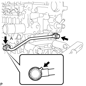
Install the No. 1 turbo oil pipe and 2 new gaskets with the 2 union bolts.
- Torque:
- 35 N*m { 357 kgf*cm, 26 ft.*lbf }
Tech Tips
Be sure to install union bolt A so that the gasket is positioned as shown in the illustration.
-
-
INSTALL NO. 3 WATER BY-PASS PIPE
-
Apply soapy water to a new O-ring and install it to the No. 3 water by-pass pipe.
-
Install the No. 3 water by-pass pipe with the 2 bolts.
- Torque:
- 21 N*m { 214 kgf*cm, 15 ft.*lbf }
-
-
INSTALL SUPPLY PUMP ASSEMBLY
-
Install a new O-ring to the supply pump assembly.
-
Install the No. 1 supply pump drive coupling.
Tech Tips
Align the No. 1 supply pump drive coupling with the groove in the camshaft end.
Note
When reusing the No. 1 supply pump drive coupling, it must be installed in the same orientation (top/bottom, front/back) as when it was removed.
-
Install the supply pump assembly with the 2 bolts.
- Torque:
- 21 N*m { 209 kgf*cm, 15 ft.*lbf }
Tech Tips
Align the end of the supply pump drive shaft with the No. 1 supply pump drive coupling.
Note
Apply engine oil to the O-ring of the supply pump assembly.
-
-
INSTALL NO. 3 FUEL HOSE
-
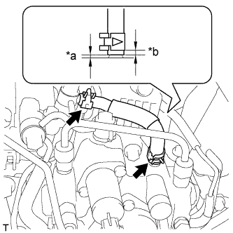
Text in Illustration *a 2 to 3 mm (0.0787 to 0.118 in.) *b 2 to 6 mm (0.0787 to 0.236 in.) Using pliers, grip the claws of the 2 clips and slide the 2 clips to install the No. 3 fuel hose to the fuel supply pump assembly and No. 2 nozzle leakage pipe.
Tech Tips
-
Push on the No. 3 fuel hose so that the clearance is 2 to 3 mm (0.0787 to 0.118 in.).
-
Position the clamp so that the distance from the end of the No. 3 hose is 2 to 6 mm (0.0787 to 0.236 in.).
-
-
-
INSTALL FUEL INJECTOR SEAL (for DPF)
-
Install a new fuel injector seal to the exhaust fuel addition injector assembly.
-
-
INSTALL EXHAUST FUEL ADDITION INJECTOR ASSEMBLY (for DPF)
Note
If there is foreign matter on the installation surface of the exhaust fuel addition injector assembly, be sure to clean the exhaust fuel addition injector assembly before installation.
-
Install a new gasket, the exhaust fuel addition injector assembly, the nozzle holder clamp, and the washer with the bolt.
- Torque:
- 29 N*m { 296 kgf*cm, 21 ft.*lbf }
Tech Tips
Align the nozzle holder clamp with the cutouts of the injector as shown in the illustration.
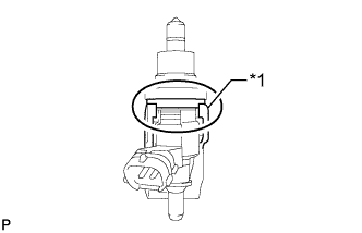
Text in Illustration *1 Nozzle Holder Clamp
-
-
INSTALL FUEL TUBE SUB-ASSEMBLY (for DPF)
-
Temporarily install the fuel tube sub-assembly and 2 new gaskets with the check valve and union bolt.
-
Tighten the check valve.
- Torque:
- 32 N*m { 321 kgf*cm, 23 ft.*lbf }
-
Tighten the union bolt.
- Torque:
- 23 N*m { 235 kgf*cm, 17 ft.*lbf }
-
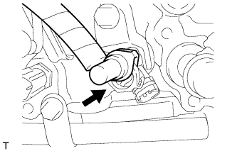
Connect the fuel tube connector to the exhaust fuel addition injector assembly.
-
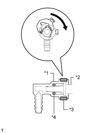
Text in Illustration *1 Fuel Tube Connector *2 Exhaust Fuel Addition Injector Assembly *3 Retainer *4 O-Ring Turn the retainer in the direction indicated by the arrow until it makes a "click" sound.
Note
If the fuel tube connector is not inserted to the correct position on the exhaust fuel addition injector assembly, the retainer cannot be turned far enough in the direction of the arrow.
-
Connect the exhaust fuel addition injector connector.
-
-
INSTALL FUEL HOSE PROTECTOR (for DPF)
-
Install the fuel hose protector with the bolt.
- Torque:
- 21 N*m { 209 kgf*cm, 15 ft.*lbf }
-
-
INSTALL NO. 2 FUEL PIPE (for CCo)
-
Temporarily install the No. 2 fuel pipe and 2 new gaskets with the check valve and union bolt.
-
Tighten the check valve.
- Torque:
- 32 N*m { 321 kgf*cm, 23 ft.*lbf }
-
Tighten the union bolt.
- Torque:
- 23 N*m { 235 kgf*cm, 17 ft.*lbf }
-
-
INSTALL NO. 2 WATER BY-PASS PIPE
-
Install a new O-ring to the No. 2 water by-pass pipe.
-
Install the No. 2 water by-pass pipe with the 2 bolts.
- Torque:
- 11 N*m { 112 kgf*cm, 8 ft.*lbf }
-
-
INSTALL NO. 4 WATER BY-PASS HOSE
-
Install the No. 4 water by-pass hose to the water inlet housing and cylinder head sub-assembly, and slide the 2 clamps to secure it.
-
-
INSTALL NO. 8 WATER BY-PASS HOSE
-
Install the No. 8 water by-pass hose to the No. 3 water by-pass pipe, and slide the clamp to secure it.
-
-
INSTALL NO. 6 WATER BY-PASS HOSE
-
Install the No. 6 water by-pass hose to the water outlet, and slide the clamp to secure it.
-
-
INSTALL WATER BY-PASS HOSE
-
Install the water by-pass hose to the water outlet and oil cooler assembly, and slide the 2 clamps to secure it.
Tech Tips
Make sure the claws of hose clamp A are positioned above the paint mark as shown in the illustration.
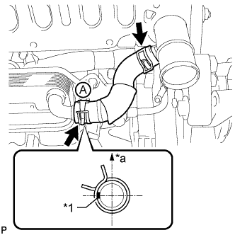
Text in Illustration *1 Paint Mark *a Upper Side
-
-
INSTALL NO. 1 CYLINDER BLOCK INSULATOR
-
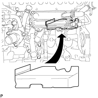
Install the No. 1 cylinder block insulator to the cylinder block.
Note
Be sure to install the oil cooler assembly before installing the No. 1 cylinder block insulator.
-
-
INSTALL GLOW PLUG ASSEMBLY
-
Using a 10 mm deep socket wrench, install the 4 glow plug sub-assemblies.
- Torque:
- 12 N*m { 125 kgf*cm, 9 ft.*lbf }
-
Install the glow plug connector with the 4 nuts.
- Torque:
- 2.2 N*m { 22 kgf*cm, 19 in.*lbf }
-
Install the 4 glow plug screw grommets.
-
-
INSTALL INTAKE MANIFOLD
-
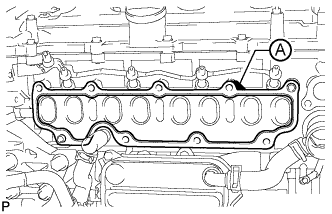
Install a new gasket to the cylinder head.
Tech Tips
Install the gasket with the part labeled A facing the right side of the vehicle as shown in the illustration.
-
Text in Illustration *1 Nut Install the intake manifold with the 7 bolts and 2 nuts.
- Torque:
- 23 N*m { 235 kgf*cm, 17 ft.*lbf }
Bolt Length Item Length Bolt A 90 mm (3.54 in.) Bolt B 25 mm (0.984 in.)
-
-
INSTALL NO. 2 INTAKE MANIFOLD
-
Install a new gasket and the No. 2 intake manifold with the bolt and 2 nuts.
- Torque:
- 24 N*m { 245 kgf*cm, 18 ft.*lbf }
-
-
INSTALL ENGINE COVER BRACKET
-
Install the engine cover bracket with the bolt.
- Torque:
- 20 N*m { 204 kgf*cm, 15 ft.*lbf }
-
-
INSTALL GAS FILTER BRACKET
-
Install the gas filter bracket with the 2 bolts.
- Torque:
- 8.8 N*m { 90 kgf*cm, 78 in.*lbf }
-
-
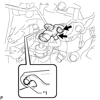
INSTALL NO. 1 GAS FILTER
-
Text in Illustration *1 Protrusion *2 Groove Install the No. 1 gas filter to the gas filter bracket.
Note
Make sure the protrusion of the No. 1 gas filter is aligned with the groove of the gas filter bracket.
-
Connect the vacuum hose.
-
-
INSTALL DIESEL TURBO PRESSURE SENSOR
-
Text in Illustration *1 Protrusion Install the diesel turbo pressure sensor with the bolt.
- Torque:
- 8.8 N*m { 90 kgf*cm, 78 in.*lbf }
Note
Make sure the protrusion of the gas filter bracket is inserted into the hole of the diesel turbo pressure sensor.
-
Connect the vacuum hose.
-
-
INSTALL INTAKE MANIFOLD INSULATOR
-
Install the intake manifold insulator to the intake manifold.
-
-
INSTALL COMMON RAIL ASSEMBLY
-
Install the common rail assembly with the 2 bolts.
- Torque:
- 21 N*m { 209 kgf*cm, 15 ft.*lbf }
-
-
INSTALL NO. 4 FUEL HOSE
-
Install the No. 4 fuel hose to the No. 2 nozzle leakage pipe and common rail assembly, and slide the 2 clamps to secure it.
-
-
INSTALL INJECTION PIPE
-
Using a 14 mm union nut wrench, tighten the 4 union nuts at the common rail end of the injection pipes.
- Torque:
- 30 N*m { 306 kgf*cm, 22 ft.*lbf }
Note
Use the formula to calculate special torque values for situations where a union nut wrench is combined with a torque wrench Click here.
-
Using a 14 mm union nut wrench, tighten the 4 union nuts at the injector end of the injection pipes.
- Torque:
- 30 N*m { 306 kgf*cm, 22 ft.*lbf }
Note
Use the formula to calculate special torque values for situations where a union nut wrench is combined with a torque wrench Click here.
-
Install the 4 No. 2 injection pipe clamps with the 2 bolts.
- Torque:
- 5.0 N*m { 51 kgf*cm, 44 in.*lbf }
-
-
INSTALL FUEL INLET PIPE SUB-ASSEMBLY
-
Temporarily install the fuel inlet pipe sub-assembly with the 2 No. 2 injection pipe clamps and nut.
-
Using a 14 mm union nut wrench, first tighten the nut at the common rail assembly end of the fuel inlet pipe sub-assembly.
- Torque:
- 30 N*m { 306 kgf*cm, 22 ft.*lbf }
Note
Use the formula to calculate special torque values for situations where a union nut wrench is combined with a torque wrench Click here.
-
Using a 14 mm union nut wrench, tighten the nut at the fuel supply pump assembly end of the fuel inlet pipe sub-assembly.
- Torque:
- 30 N*m { 306 kgf*cm, 22 ft.*lbf }
Note
Use the formula to calculate special torque values for situations where a union nut wrench is combined with a torque wrench Click here.
-
Tighten the No. 2 injection pipe clamp nut.
- Torque:
- 5.0 N*m { 51 kgf*cm, 44 in.*lbf }
-
-
INSTALL ENGINE OIL LEVEL DIPSTICK GUIDE
-
Install a new O-ring to the engine oil level dipstick guide.
-
Install the engine oil level dipstick guide with the 2 bolts.
- Torque:
- 24 N*m { 245 kgf*cm, 18 ft.*lbf }
-
Install the engine oil level dipstick.
-
-
INSTALL ELECTRIC EGR CONTROL VALVE ASSEMBLY
-
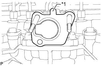
Обозначения на рисунке *1 Выступ Установите новую прокладку.
Tech Tips
Убедитесь, что выступ прокладки обращен вверх, как показано на рисунке.
-
Установите электрический клапан управления РОГ в сборе.
-
-
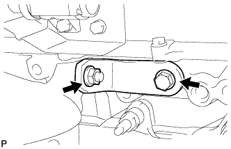
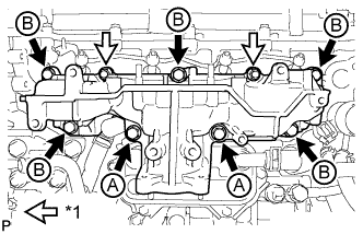
INSTALL NO. 2 EGR PIPE SUB-ASSEMBLY
-
Установите 2 новые прокладки на трубу РОГ № 2 и электрический клапан РОГ.
-
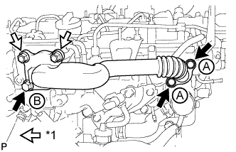
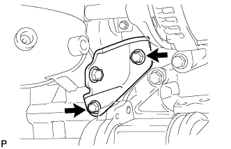
Обозначения на рисунке *1 Гайка Временно закрепите трубу РОГ № 2 в сборе 3 болтами и 2 гайками.
Стандартный болт Параметр / Устройство Длина Болт A 25 мм (0,984 дюйма) Болт B 70 мм (2,76 дюйма) -
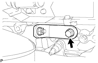
Затяните 2 болта, обозначенные А, как показано на рисунке.
- Torque:
- 24 Н*м { 245 кгс*см, 18 фунт-сила-футов }
-
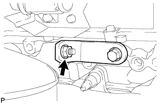
Затяните болт B и 2 гайки, показанные на рисунке.
- Torque:
- 24 Н*м { 245 кгс*см, 18 фунт-сила-футов }
-
Подсоедините разъем электрического клапана управления РОГ.
-
-
INSTALL EGR VALVE BRACKET
-
Install the 2 EGR valve brackets with the 3 bolts.
- Torque:
- 24 N*m { 245 kgf*cm, 18 ft.*lbf }
-
-
CONNECT NO. 8 WATER BY-PASS HOSE
-
Подсоедините перепускной шланг охлаждающей жидкости № 8 к электрическому клапану РОГ и надвиньте хомут, чтобы закрепить его.
-
-
INSTALL NO. 7 WATER BY-PASS HOSE
-
Подсоедините перепускной шланг охлаждающей жидкости № 7 к электрическому клапану РОГ и надвиньте хомут, чтобы закрепить его.
-
-
INSTALL DIESEL THROTTLE BODY ASSEMBLY
-
Install a new gasket and the diesel throttle body assembly with the 2 bolts and 2 nuts.
- Torque:
- 11 N*m { 112 kgf*cm, 8 ft.*lbf }
-
Connect the No. 6 water by-pass hose and No. 7 water by-pass hose to the diesel throttle body assembly, and slide the 2 clamps to secure it.
-
-
INSTALL VACUUM PUMP ASSEMBLY
-
Apply a light coat of engine oil to 2 new O-rings.
-
Install the 2 O-rings to the vacuum pump assembly.
-
Install the vacuum pump assembly with 3 new bolts.
- Torque:
- 21 N*m { 214 kgf*cm, 15 ft.*lbf }
-
Connect the vacuum hose.
-
-
INSTALL V-RIBBED BELT TENSIONER ASSEMBLY
-
Install the V-ribbed belt tensioner assembly with the 3 bolts.
- Torque:
- 20 N*m { 204 kgf*cm, 15 ft.*lbf }
Note
As the bolt heads are not as thick as typical bolts, be careful not to damage them during installation.
-
-
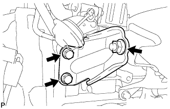
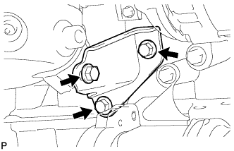
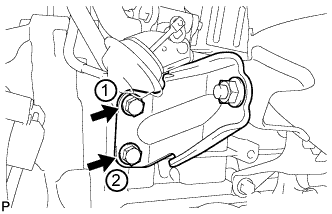
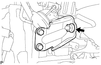
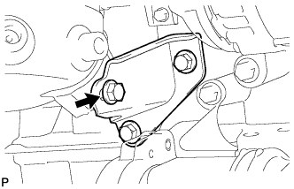
INSTALL ENGINE MOUNTING BRACKET
-
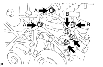
Set the engine mounting bracket on the engine.
-
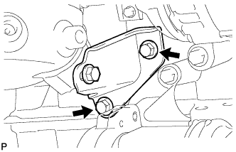
Temporarily install the 2 bolts labeled B and 2 nuts.
-
Install the 2 bolts labeled A.
- Torque:
- 28 N*m { 286 kgf*cm, 21 ft.*lbf }
-
Tighten the 2 bolts labeled B and 2 nuts.
- Torque:
- 80 N*m { 816 kgf*cm, 59 ft.*lbf }
-
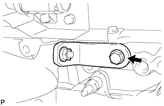
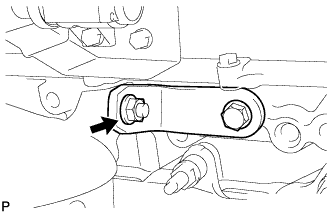
Install the stud bolt to the engine mounting bracket.
- Torque:
- 10 N*m { 102 kgf*cm, 7 ft.*lbf }
-
-
INSTALL NO. 4 WATER BY-PASS PIPE
-
Install a new O-ring to the No. 4 water by-pass pipe.
-
Install the No. 4 water by-pass pipe with the bolt.
- Torque:
- 11 N*m { 112 kgf*cm, 8 ft.*lbf }
-
-
INSTALL NO. 1 IDLER PULLEY SUB-ASSEMBLY
-
Install the No. 1 idler pulley sub-assembly with the bolt.
- Torque:
- 40 N*m { 408 kgf*cm, 30 ft.*lbf }
-
-
INSTALL IDLER PULLEY COVER PLATE
-
Install the idler pulley cover plate.
-
-
INSTALL NO. 2 IDLER PULLEY SUB-ASSEMBLY
-
Install the No. 2 idler pulley sub-assembly and No. 2 idler pulley cover plate with the bolt.
- Torque:
- 40 N*m { 408 kgf*cm, 30 ft.*lbf }
-
-
INSTALL GENERATOR ASSEMBLY
-
Install the generator assembly with the 3 bolts.
- Torque:
- 25 N*m { 255 kgf*cm, 18 ft.*lbf }
-
-
INSTALL COMPRESSOR STAY
-
Install the compressor stay to the cylinder block sub-assembly.
- Torque:
- 35 N*m { 357 kgf*cm, 26 ft.*lbf }
-
-
INSTALL COMPRESSOR WITH PULLEY ASSEMBLY (w/ Air Conditioning System)
-
Using an E8 "TORX" socket wrench, install the compressor with pulley assembly with the 2 stud bolts.
- Torque:
- 9.8 N*m { 100 kgf*cm, 87 in.*lbf }
-
Install the 2 bolts and 2 nuts.
- Torque:
- 25 N*m { 255 kgf*cm, 18 ft.*lbf }
-
Connect the connector.
-
-
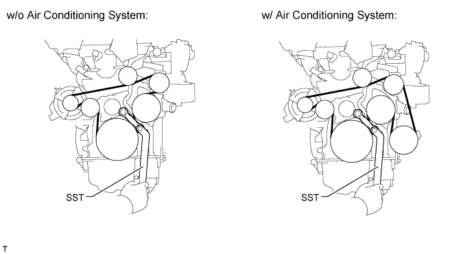
INSTALL FAN AND GENERATOR V BELT
-
Using SST and a 22 mm wrench, rotate the tensioner pulley counterclockwise, and then install the fan and generator V belt.
- SST
- 09216-42010
CAUTION:
-
Be careful as the wrench only fits loosely on the belt tensioner tool set point. The wrench may come off the set point and cause injuries.
-
Be careful that your hands do not become jammed between parts such as the belt, pulleys, etc.
Note
-
Make sure that the belt is set properly on each pulley.
-
Make sure SST is installed as shown in the illustration. If not, SST and/or the belt may not be able to be removed.
-