-
When replacing the injectors (including shuffling the injectors between the cylinders), common rail, intake manifold or cylinder head, it is necessary to replace the injection pipes with new ones.
-
When replacing the fuel supply pump, common rail, intake manifold or cylinder head, it is necessary to replace the fuel inlet pipe with a new one.
- Click here
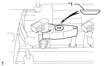
INSTALL CYLINDER BLOCK DRAIN COCK PLUG
-
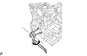
Apply adhesive to the cylinder block drain cock plug.
Seal packing Toyota Genuine Seal Packing 1282B, Three Bond 1282B or equivalent -
Install the cylinder block drain cock plug.
25 N*m 255 kgf*cm 18 ft.*lbf
-
- Click here
INSTALL OIL BAFFLE PLATE
-
Install the oil baffle plate with the 4 bolts.
32 N*m 321 kgf*cm 23 ft.*lbf
-
- Click here
INSTALL REAR CRANKSHAFT OIL SEAL
-
Apply MP grease to the lip of a new rear crankshaft oil seal.
-
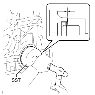
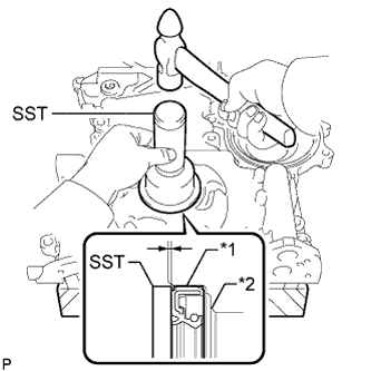
Using SST and a hammer, tap in the rear crankshaft oil seal as shown in the illustration.
09223-56010 Standard depth 0 to 0.9 mm (0 to 0.0354 in.) Note:
-
Keep the lip free from foreign matter.
-
Do not tap the rear crankshaft oil seal at an angle.
-
Make sure that the rear crankshaft oil seal is properly installed.
-
-
- Click here
SELECT CYLINDER HEAD GASKET
-
Check the piston protrusions for each cylinder.
-
Clean the cylinder block sub-assembly with solvent.
-
Set the piston of the cylinder to be measured to slightly before TDC.
-
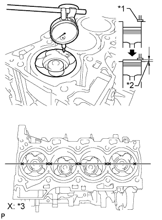
Place a dial indicator on the cylinder block sub-assembly, and set the measuring tip as shown in the illustration.
Table 1. Text in Illustration *1 Measuring Tip *2 Protrusion *3 Measuring Point -
Set the dial indicator at 0 mm (0 in.).
Tip:Make sure that the measuring tip is perpendicular to the cylinder block gasket surface and piston head when taking the measurements.
-
Find where the piston head protrudes most by slowly turning the crankshaft clockwise and counterclockwise.
-
Measure each cylinder at 2 places as shown in the illustration, making a total of 8 measurements.
-
For the piston protrusion value of each cylinder, use the average of the 2 measurements of each cylinder.
Standard piston protrusion 0.300 to 0.560 mm (0.0118 to 0.0220 in.) If the protrusion is not as specified, remove the piston and connecting rod and reinstall it.
-
-
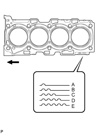
Select a new cylinder head gasket.
New Installed Cylinder Head Gasket Thickness Cutout Mark Specified Condition A 1.00 to 1.10 mm (0.0394 to 0.0433 in.) B 1.05 to 1.15 mm (0.0413 to 0.0453 in.) C 1.10 to 1.20 mm (0.0433 to 0.0472 in.) D 1.15 to 1.25 mm (0.0453 to 0.0492 in.) E 1.20 to 1.30 mm (0.0472 to 0.0512 in.) Table 2. Text in Illustration 
Front Tip:Cylinder head gaskets are marked A, B, C, D or E accordingly.
-
Select the largest piston protrusion value from the measurements and then select a new appropriate gasket according to the table below.
Table 3. Gasket Size Item Specified Condition Piston protrusion 0.300 to 0.355 mm (0.0118 to 0.0140 in.) 0.355 to 0.405 mm (0.0140 to 0.0159 in.) 0.405 to 0.455 mm (0.0159 to 0.0179 in.) 0.455 to 0.505 mm (0.0179 to 0.0199 in.) 0.505 to 0.560 mm (0.0199 to 0.0220 in.) Gasket to be used A B C D E
-
-
- Click here
INSTALL CYLINDER HEAD GASKET
- Click here
INSTALL CYLINDER HEAD SUB-ASSEMBLY
-
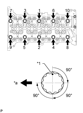
Using the crankshaft pulley bolt, set the No. 1 cylinder to 90° BTDC/compression.
-
Place the cylinder head gasket in position on the cylinder block sub-assembly.
-
Place the cylinder head sub-assembly on the cylinder head gasket.
Note:Be careful of the installation direction.
-
Apply a light coat of engine oil to the threads and under the heads of the cylinder head bolts.
-
Temporarily install the cylinder head bolts.
Tip:If any cylinder head bolt is broken or deformed, replace it.
-
Step 1:
For new bolts, perform steps 1 to 3. For used bolts, perform only step 1.
-
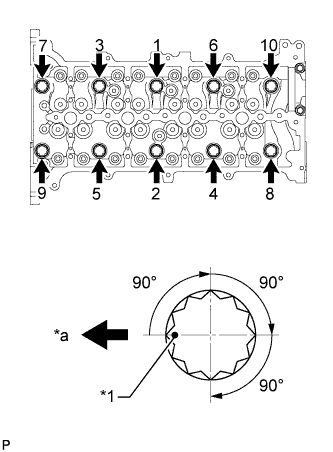
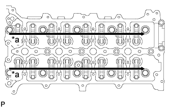
Uniformly tighten the 10 cylinder head bolts, in several steps in the sequence shown in the illustration.
50 N*m 510 kgf*cm 37 ft.*lbf Table 4. Text in Illustration *1 Paint Mark *a Front Tip:If any one of the cylinder head bolts does not meet the torque specification, replace the cylinder head bolt.
-
Mark the front of the cylinder head bolts with paint.
-
Tighten the cylinder head bolts by 90° in the sequence shown in the illustration.
-
Perform the step above twice.
-
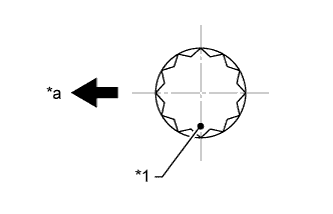
Check that the paint marks are positioned as shown in the illustration.
Table 5. Text in Illustration *1 Paint Mark *a Front
-
-
Step 2:
-
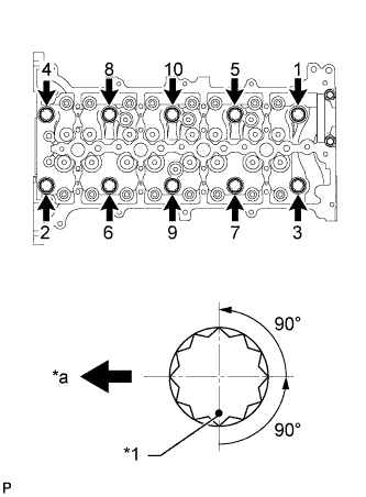
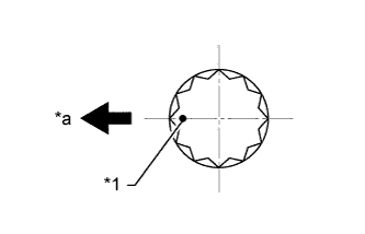
Loosen the cylinder head bolts by 90° in the sequence shown in the illustration.
Table 6. Text in Illustration *1 Paint Mark *a Front -
Perform the step above again.
-
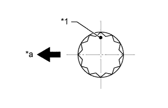
Check that the paint marks are positioned as shown in the illustration.
Table 7. Text in Illustration *1 Paint Mark *a Front
-
-
Step 3:
-
Retighten the cylinder head bolts by 90° in the sequence shown in the illustration.
Table 8. Text in Illustration *1 Paint Mark *a Front -
Perform the above step twice.
-
Check that the paint marks are positioned as shown in the illustration.
Table 9. Text in Illustration *1 Paint Mark *a Front
-
-
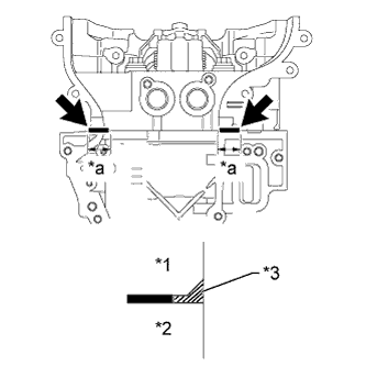
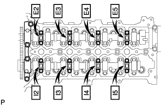
Apply seal packing between the cylinder head sub-assembly and cylinder block sub-assembly in the areas shown in the illustration.
Seal packing Toyota Genuine Seal Packing Black, Three Bond 1207B or equivalent Standard seal packing application length 15 mm (0.591 in.) or more Table 10. Text in Illustration *1 Cylinder Head Sub-assembly *2 Cylinder Block Sub-assembly *3 Seal Packing *a 15 mm or more Note:
-
Before applying seal packing, clean the cylinder head sub-assembly and cylinder block sub-assembly surfaces near the head gasket. Be sure to remove any oil that has seeped in between the cylinder head gasket and cylinder head sub-assembly or cylinder block sub-assembly.
-
When the contact surfaces are wet, wipe them off with an oil-free cloth before applying seal packing.
-
Wipe off any seal packing that seeps out from the groove in the cylinder head sub-assembly.
-
Do not start the engine for at least 4 hours after installation.
-
-
- Click here
INSPECT VALVE LASH ADJUSTER ASSEMBLY
Note:
-
Keep the valve lash adjuster free from dirt and foreign objects.
-
Use only clean engine oil.
-
Place the valve lash adjuster assembly into a container full of new engine oil.
-
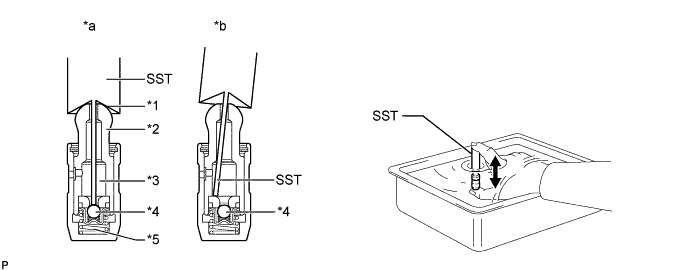
Insert SST tip into the valve lash adjuster plunger and use the tip to press down on the check ball inside the plunger.
09276-75010 Table 11. Text in Illustration *1 Taper Port *2 Plunger *3 Lower Pressure Chamber *4 Check Ball *5 High Pressure Chamber - - *a CORRECT *b INCORRECT -
Squeeze SST and the valve lash adjuster together to move the plunger up and down 5 to 6 times.
-
Check the movement of the plunger and bleed air.
OK Plunger moves up and down. Note:When bleeding high-pressure air from the compression chamber, make sure that the tip of SST is actually pressing the check ball as shown in the illustration. If the check ball is not pressed, air will not bleed.
-
After bleeding air, remove SST. Then quickly and firmly press the plunger repeatedly with your fingers.
OK Plunger can be pressed 3 times. If the plunger can still be compressed after pressing it 3 times, replace the valve lash adjuster assembly with a new one.
-
- Click here
INSTALL VALVE LASH ADJUSTER ASSEMBLY
-
Install the 16 valve lash adjuster assemblies to the cylinder head sub-assembly.
Note:Install the valve lash adjuster assemblies to their original positions.
-
- Click here
INSTALL NO. 1 VALVE ROCKER ARM SUB-ASSEMBLY
-
Install the 16 No. 1 valve rocker arm sub-assemblies to the valve lash adjuster assemblies.
-
- Click here
INSTALL CAMSHAFT
-
Install the No. 2 camshaft bearing cap.
-
Apply clean engine oil to the cam of each camshaft, journals of the cylinder head sub-assembly and No. 1 valve rocker arm sub-assemblies.
Table 12. Text in Illustration *a Apply Engine Oil -
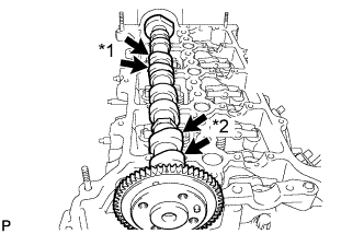
Place the No. 2 camshaft on the cylinder head sub-assembly as shown in the illustration so that the No. 1 cylinder cam lobe and No. 3 cylinder cam lobe face upward.
Table 13. Text in Illustration *1 No. 3 Cylinder Cam Lobe *2 No. 1 Cylinder Cam Lobe Note: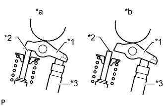
Before and after setting the camshaft and No. 2 camshaft on the cylinder head sub-assembly, check that the No. 1 valve rocker arm sub-assembly is firmly set to the valve lash adjuster assembly.
Table 14. Text in Illustration *1 No. 1 Valve Rocker Arm Sub-assembly *2 Valve Stem *3 Valve Lash Adjuster Assembly *a CORRECT *b INCORRECT -
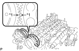
Align the camshaft and No. 2 camshaft timing mark (1 dot mark each).
Table 15. Text in Illustration *1 Dot Mark -
Place the camshaft on the cylinder head sub-assembly.
-
Set the 8 No. 3 camshaft bearing caps and No. 1 camshaft bearing cap on the camshafts as shown in the illustration.
Tip:Make sure of the marks and numbers on the camshaft bearing caps and place them in the proper position and direction.
-
Partially tighten the 20 bolts.
-
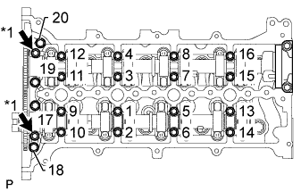
Uniformly tighten the bolts in several steps, in the sequence shown in the illustration.
for 1 to 16 10 N*m 102 kgf*cm 7 ft.*lbf for 17 to 20 21 N*m 214 kgf*cm 15 ft.*lbf -
Install the 2 oil pipe seats.
17 N*m 173 kgf*cm 13 ft.*lbf Table 16. Text in Illustration *1 Oil Pipe Seat
-
- Click here
INSTALL KEY
-
Install the 2 keys to the crankshaft.
-
- Click here
INSTALL CAMSHAFT TIMING SPROCKET
-
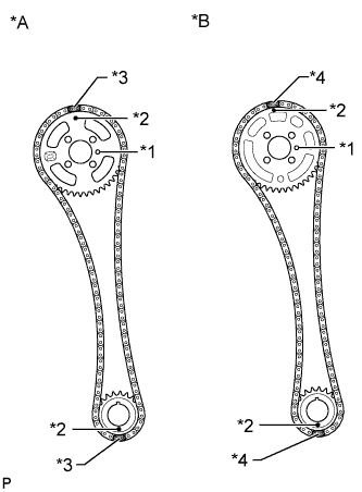
Install the crankshaft timing sprocket and camshaft timing sprocket to the chain sub-assembly so that the timing marks of the sprockets and paint marks of the chain sub-assembly are aligned.
Table 17. Text in Illustration *A CCo *B DPF *1 Straight Pin *2 Timing Mark *3 Yellow Paint Mark *4 Pink Paint Mark -
Install the camshaft timing sprocket to the No. 2 camshaft by fitting the straight pin of the No. 2 camshaft into the hole on the camshaft timing sprocket.
-
Install the crankshaft timing sprocket to the crankshaft.
-
While holding the hexagon portion of the No. 2 camshaft, install and uniformly tighten the 4 bolts of the No. 2 camshaft.
20 N*m 204 kgf*cm 15 ft.*lbf
-
- Click here
INSTALL OIL PUMP DRIVE GEAR
-
Install the oil pump drive gear to the crankshaft.
-
- Click here
INSTALL NO. 1 CHAIN VIBRATION DAMPER
-
Install the No. 1 chain vibration damper with the 2 bolts.
21 N*m 214 kgf*cm 15 ft.*lbf
-
- Click here
INSTALL CHAIN TENSIONER SLIPPER
-
Install the chain tensioner slipper.
-
- Click here
INSTALL NO. 1 CHAIN TENSIONER ASSEMBLY
-
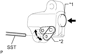
Move the stopper plate upward to release the lock, and push the plunger deep into the No. 1 chain tensioner assembly.
Table 18. Text in Illustration *1 Plunger *2 Stopper Plate -
Move the stopper plate downward to set the lock, and insert SST into the stopper plate hole.
09240-00020 09242-00200 -
Install the No. 1 chain tensioner assembly with the 2 bolts.
9.0 N*m 92 kgf*cm 80 in.*lbf -
Remove SST.
-
- Click here
INSTALL FRONT CRANKSHAFT OIL SEAL
-
Using SST and a hammer, tap in a new front crankshaft oil seal until its surface is flush with the timing chain cover sub-assembly edge.
09223-50010 Standard depth 0 to 0.6 mm (0 to 0.236 in.) Table 19. Text in Illustration *1 Front Crankshaft Oil Seal *2 Timing Chain Cover Sub-assembly Note:
-
Keep the lip of the front crankshaft oil seal free from foreign matter.
-
Do not tap in the front crankshaft oil seal at an angle.
-
-
Apply MP grease to the lip of the front crankshaft oil seal.
Note:
-
Do not allow foreign matter to contact the lip of the front crankshaft oil seal.
-
Do not allow MP grease to contact the dust seal.
-
-
- Click here
INSTALL TIMING CHAIN COVER SUB-ASSEMBLY
-
Install a new gasket and O-ring to the timing chain cover sub-assembly.
-
Remove any old seal packing material.
-
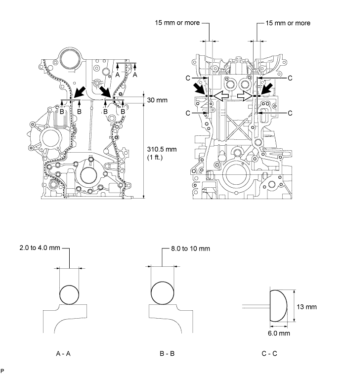
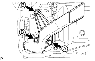
Apply seal packing in a continuous line to the timing chain cover sub-assembly as shown in the following illustration.
Seal packing Toyota Genuine Seal Packing Black, Three Bond 1207B or equivalent Apply Seal Packing as Follows Area Seal Packing Diameter (Round) Seal Packing Dimension (Flat) Seal Packing Application Length A - A 2.0 to 4.0 mm (0.0787 to 0.157 in.) - - B - B 8.0 to 10 mm (0.315 to 0.394 in.) - 30 mm (1.18 in.) C - C - 13 mm (0.512 in.) or more wide and 6.0 mm (0.236 in.) or more thick 15 mm (0.591 in.) Note:
-
Be sure to clean and degrease the contact surfaces, especially the 4 areas indicated by the arrows in the illustration.
-
When the contact surfaces are wet, wipe them off with an oil-free cloth before applying seal packing.
-
When applying seal packing to area C - C, apply it in the direction of the white arrows in the illustration.
-
Install the timing chain cover sub-assembly within 3 minutes and tighten the bolts within 15 minutes after applying seal packing.
-
Do not start the engine for at least 4 hours after installation.
-
-
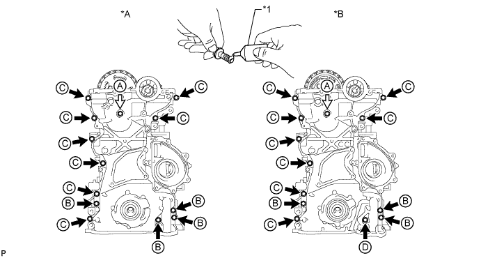
for CCo:
Apply adhesive to the 4 bolts labeled B.
Adhesive Toyota Genuine Adhesive 1324, Three Bond 1324 or equivalent Table 20. Text in Illustration *A for CCo *B for DPF *1 Adhesive - - 
Bolt and New Seal Washer - - -
for DPF:
Apply adhesive to the 3 bolts labeled B and bolt labeled D.
Adhesive Toyota Genuine Adhesive 1324, Three Bond 1324 or equivalent -
Temporarily install the timing chain cover sub-assembly and a new seal washer with the 13 bolts.
Bolt Length Item Specified Condition Bolt A 60 mm (2.36 in.) Bolt B 30 mm (1.18 in.) Bolt C 30 mm (1.18 in.) Bolt D 45 mm (1.77 in.) Tip:Bolt B and C are identical.
-
for CCo:
Tighten the 12 bolts labeled B and C.
23 N*m 229 kgf*cm 17 ft.*lbf -
for DPF:
Tighten the 12 bolts labeled B, C and D.
23 N*m 229 kgf*cm 17 ft.*lbf -
Tighten the bolt labeled A.
21 N*m 214 kgf*cm 15 ft.*lbf
-
- Click here
INSTALL CRANKSHAFT PULLEY
-
Align the keyway of the crankshaft pulley with the key located on the crankshaft, and then slide the crankshaft pulley into place to install it.
-
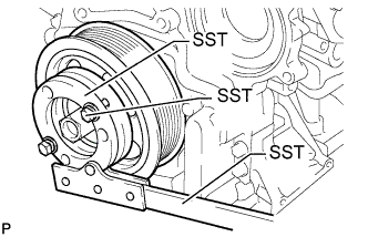
Using SST, install a new pulley bolt.
09213-58014 91551-80840 09330-00021 300 N*m 3059 kgf*cm 221 ft.*lbf
-
- Click here
INSTALL OIL STRAINER SUB-ASSEMBLY
-
Install a new O-ring to the oil strainer sub-assembly.
-
Apply a light coat of engine oil to the O-ring.
-
Install the oil strainer sub-assembly with the 3 bolts.
for bolt A 42 N*m 428 kgf*cm 31 ft.*lbf for bolt B 9.0 N*m 92 kgf*cm 80 in.*lbf
-
- Click here
INSTALL OIL FILTER BRACKET
-
Install a new gasket to the oil filter bracket.
-
Install the oil filter bracket with the 4 bolts.
9.0 N*m 92 kgf*cm 80 in.*lbf
-
- Click here
INSTALL OIL PRESSURE SWITCHING VALVE ASSEMBLY (for DPF)
- Click here
INSTALL OIL FILTER ELEMENT
-
Clean the inside of the oil filter cap, its threads and its O-ring groove.
-
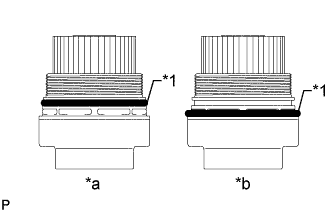
Apply a small amount of engine oil to a new O-ring and install it to the oil filter cap.
Table 21. Text in Illustration *1 O-Ring *a CORRECT *b INCORRECT Note:
-
Be sure to install the O-ring in the proper location, otherwise oil may leak.
-
Do not twist the O-ring.
-
-
Set a new oil filter element in the oil filter cap.
-
Remove any dirt or foreign matter from the installation surface of the engine.
-
Apply a small amount of engine oil to the O-ring again and temporarily install the oil filter cap.
-
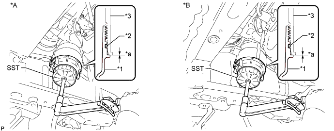
Using SST, tighten the oil filter cap.
09228-06501 25 N*m 255 kgf*cm 18 ft.*lbf *A for CCo *B for DPF *1 Oil Filter Cap *2 O-Ring *3 Oil Filter Bracket - - *a No Gap - - Note:After tightening the oil filter cap, make sure that there is no gap and that the O-ring is not protruding.
-
- Click here
INSTALL NO. 2 OIL PAN SUB-ASSEMBLY
-
Remove any old seal packing material.
-
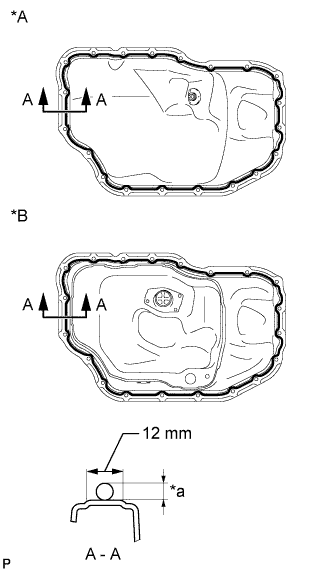
Apply seal packing in a continuous line as shown in the illustration.
Seal packing Toyota Genuine Seal Packing Black, Three Bond 1207B or equivalent Standard Seal Packing Dimension Area Seal Packing Diameter Acceptable Seal Packing Application Range A - A 4.0 to 7.0 mm (0.157 to 0.276 in.) 12 mm (0.472 in.) Table 22. Text in Illustration *A for CCo *B for DPF *a 4.0 to 7.0 mm Note:
-
Remove any oil from the contact surface.
-
Install the No. 2 oil pan sub-assembly within 3 minutes and tighten the bolts within 10 minutes after applying seal packing.
-
Do not start the engine for at least 4 hours after installation.
-
-
Install the No. 2 oil pan sub-assembly with the 18 bolts and 2 nuts.
11 N*m 107 kgf*cm 8 ft.*lbf
-
- Click here
INSTALL CYLINDER HEAD COVER SUB-ASSEMBLY
-
Remove any old seal packing material.
-
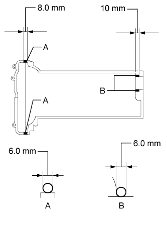
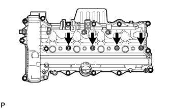
Apply seal packing to the cylinder head as shown in the illustration.
Seal packing Toyota Genuine Seal Packing Black, Three Bond 1207B or equivalent Standard Seal Packing Dimension Area Seal Packing Diameter Seal Packing Application Length A 6.0 mm (0.236 in.) 8.0 mm (0.315 in.) B 6.0 mm (0.236 in.) 10 mm (0.394 in.) -
Install a new cylinder head cover gasket to the cylinder head cover sub-assembly.
-
Install the cylinder head cover gasket so that the triangle tabs of the cylinder head cover gasket are aligned with the protrusions of the cylinder head cover sub-assembly as shown in the parts of the illustration labeled A and B.
-
Install the cylinder head cover gasket to the groove of the cylinder head cover sub-assembly moving from C and D in the direction of the black arrows shown in the illustration.
-
Install the cylinder head cover gasket to the groove of the cylinder head cover sub-assembly moving from C and D towards E as shown by the white arrows in the illustration.
-
Install the cylinder head gasket to the groove of the cylinder head cover sub-assembly moving from D towards F as shown by the striped arrow in the illustration.
-
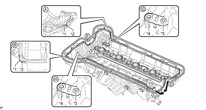
Install the cylinder head cover gasket to the cylinder head cover sub-assembly pins and cutouts as shown in the parts of the illustration labeled G and H.
Table 23. Text in Illustration *1 Triangle Tab of Cylinder Head Cover Gasket *2 Protrusion of Cylinder Head Cover Sub-assembly *3 Cylinder Head Cover Sub-assembly Pin *4 Cutout of Cylinder Head Cover Sub-assembly Note: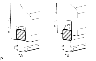
Make sure that the rib of the cylinder head cover gasket is securely inserted into the groove of the cylinder head cover sub-assembly.
Table 24. Text in Illustration *a CORRECT *b INCORRECT 
Rib of Cylinder Head Cover Gasket
-
-
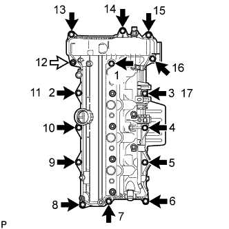
Install the cylinder head cover sub-assembly with the 14 bolts and nut, and tighten the bolts and nut in the order shown in the illustration.
10 N*m 102 kgf*cm 7 ft.*lbf Table 25. Text in Illustration Nut Tip:Partially tighten the bolt indicated by the number 6 in the illustration until the cylinder head cover sub-assembly contacts the cylinder head, and then tighten the bolts and nut in the order shown in the illustration.
-
- Click here
INSTALL NOZZLE HOLDER CLAMP SEAT
-
Install the 4 nozzle holder clamp seats.
10 N*m 102 kgf*cm 7 ft.*lbf
-
- Click here
INSTALL OIL FILLER CAP SUB-ASSEMBLY
- Click here
INSTALL WATER INLET HOUSING
-
Install a new gasket and the water inlet housing with the 3 nuts.
9.0 N*m 92 kgf*cm 80 in.*lbf
-
- Click here
INSTALL ENGINE OIL LEVEL SENSOR
-
Install the engine oil level sensor with the 4 bolts.
7.0 N*m 71 kgf*cm 62 in.*lbf
-
- Click here
INSTALL NO. 1 OIL COOLER BRACKET
-
for CCo:
-
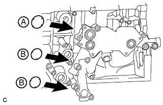
Apply engine oil to the 2 new O-rings labeled B in the illustration.
Note:Do not apply engine oil to the new O-ring labeled A in the illustration.
-
Install 3 new O-rings to the No. 1 oil cooler bracket.
-
-
for DPF:
-
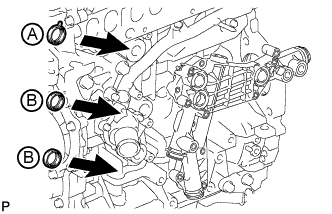
Apply engine oil to the 2 new gaskets labeled B in the illustration.
Note:Do not apply engine oil to the new gasket labeled A in the illustration.
-
Install 3 new gaskets to the No. 1 oil cooler bracket.
-
-
Install the No. 1 oil cooler bracket with the 6 bolts and nut.
10 N*m 102 kgf*cm 7 ft.*lbf
-
- Click here
INSTALL OIL COOLER ASSEMBLY
-
for CCo:
-
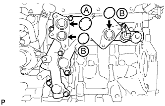
Apply engine oil to the 2 new O-rings labeled B in the illustration.
Note:Do not apply engine oil to the new O-ring labeled A in the illustration.
-
Install 3 new O-rings to the No. 1 oil cooler bracket.
-
-
for DPF:
-
Apply engine oil to the 2 new gaskets labeled B in the illustration.
Note:Do not apply engine oil to the new gasket labeled A in the illustration.
-
Install 3 new gaskets to the No. 1 oil cooler bracket.
-
-
Install the oil cooler assembly with the 5 bolts.
10 N*m 102 kgf*cm 7 ft.*lbf
-
- Click here
INSTALL ENGINE OIL PRESSURE SWITCH ASSEMBLY (for CCo)
-
Remove the adhesive from the threads of the oil pressure switch assembly and the bolt hole of the No. 1 oil cooler bracket.
-
Apply adhesive to 2 or 3 threads of the oil pressure switch assembly.
Table 26. Text in Illustration *1 Adhesive Adhesive Toyota Genuine Adhesive 1344, Three Bond 1344 or equivalent Note:Do not apply adhesive to the oil inlet port of the engine oil pressure switch assembly.
-
Using a 24 mm deep socket wrench, install the engine oil pressure switch assembly.
13 N*m 133 kgf*cm 10 ft.*lbf Note:Do not start the engine for at least 1 hour after installation.
-
Connect the engine oil pressure switch connector.
-
- Click here
INSTALL OIL PRESSURE SENDER GAUGE ASSEMBLY (for DPF)
-
Remove the adhesive from the threads of the oil pressure sender gauge assembly and the bolt hole of the No. 1 oil cooler bracket.
-
Apply adhesive to 2 or 3 threads of the oil pressure sender gauge assembly.
Adhesive Toyota Genuine Adhesive 1344, Three Bond 1344 or equivalent Note:Do not apply adhesive to the oil inlet port of the oil pressure sender gauge assembly.
-
Using a 27 mm deep socket wrench, install the oil pressure sender gauge assembly.
15 N*m 153 kgf*cm 11 ft.*lbf Note:Do not start the engine for at least 1 hour after installation.
-
Connect the oil pressure sender gauge connector.
-
- Click here
INSTALL WATER PUMP ASSEMBLY
-
Remove the adhesive from the threads of the bolt and the bolt hole of the timing chain cover sub-assembly.
-
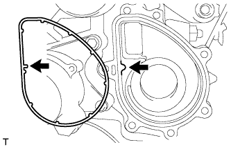
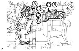
Install a new gasket to the timing chain cover sub-assembly so that the protrusions indicated by the arrows in the illustration are aligned.
-
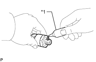
Apply adhesive to 2 or 3 threads of the bolt labeled A shown in the illustration.
Standard Bolt Length Item Specified Condition Bolt A and C 45 mm (1.77 in.) Bolt B 30 mm (1.18 in.) Adhesive Toyota Genuine Adhesive 1324, Three Bond 1324 or equivalent Table 27. Text in Illustration *a Adhesive -
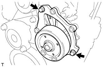
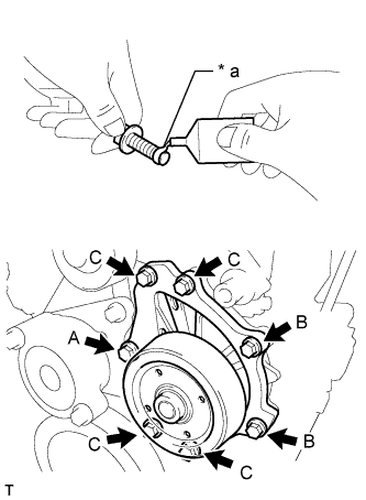
Install the water pump assembly with the 2 bolts indicated by the arrows in the illustration.
23 N*m 229 kgf*cm 17 ft.*lbf -
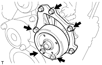
Install the 5 bolts.
23 N*m 229 kgf*cm 17 ft.*lbf
-
- Click here
INSTALL ENGINE COOLANT TEMPERATURE SENSOR
-
Install a new gasket to the engine coolant temperature sensor.
-
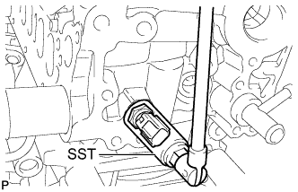
Using SST, install the engine coolant temperature sensor.
09817-33190 20 N*m 200 kgf*cm 14 ft.*lbf
-
- Click here
INSTALL CRANKSHAFT POSITION SENSOR
-
Install the crankshaft position sensor with the 2 bolts.
8.8 N*m 90 kgf*cm 78 in.*lbf -
Connect the crankshaft position sensor harness and install the clip.
-
- Click here
INSTALL CAMSHAFT POSITION SENSOR
-
Install the camshaft position sensor with the bolt.
8.8 N*m 90 kgf*cm 78 in.*lbf
-
- Click here
INSTALL INJECTOR ASSEMBLY
Note:Before installing the injector, check for carbon, foreign matter, etc. on the seal surfaces of the cylinder head and injector. If there is foreign matter, remove it before installing the injector.
-
Install 4 new injection nozzle seats to the cylinder head.
-
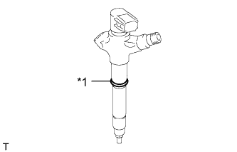
Install a new O-ring to each injector assembly.
Table 28. Text in Illustration *1 New O-Ring -
Apply a light coat of engine oil to the O-ring on each injector assembly.
-
Install the 4 injectors to the cylinder head.
Note:Fit the injectors to the injection nozzle seats.
-
Install the 4 No. 1 nozzle holder clamps and 4 washers as shown in the illustration.
Note:Pay attention to the mounting orientation (beveled edge) of the washer.
Table 29. Text in Illustration *1 Washer -
Temporarily install the nozzle holder clamp bolts.
Note:When temporarily installing the nozzle holder clamp bolt to the No. 1 nozzle holder clamp, make sure that the nozzle holder clamp bolt and No. 1 nozzle holder clamp are not at an angle.
Tip:Apply a light coat of engine oil to the threads of the nozzle holder clamp bolts.
-
Temporarily install the 4 injection pipes.
-
Temporarily install the No. 1 leakage pipe and 4 new gaskets with the 4 union bolts and bolt.
-
Tighten the 4 nozzle holder clamp bolts.
25 N*m 255 kgf*cm 18 ft.*lbf -
Connect the 4 injector connectors.
-
- Click here
INSTALL NO. 1 NOZZLE LEAKAGE PIPE
-
Install 4 new gaskets and the No. 1 nozzle leakage pipe with the 4 union bolts and bolt.
for union bolt 18 N*m 184 kgf*cm 13 ft.*lbf for bolt 21 N*m 209 kgf*cm 15 ft.*lbf
-
- Click here
INSTALL NO. 2 NOZZLE LEAKAGE PIPE
-
Temporarily install the No. 2 nozzle leakage pipe and a new gasket with the check valve and bolt.
-
Tighten the check valve.
32 N*m 321 kgf*cm 23 ft.*lbf -
Tighten the bolt.
32 N*m 321 kgf*cm 23 ft.*lbf
-