СИСТЕМА ECD White Smoke Emitted
DESCRIPTION
-
Faults and Symptoms of Common Rail Diesel Components
-
Engine Control
Turbocharger System Component Turbocharger system Main fault
-
Air leak in the turbocharged air passage
-
Turbocharger (turbine, bearing)
Symptoms Lack of power (when vehicle starting, under heavy load)
(Black smoke is not emitted when racing the engine while the vehicle is stopped)
White smoke
Data List MAP (inside intake air pressure), Target Booster Pressure
-
When the accelerator is fully depressed, if MAP is 20 kPa lower than Target Booster Pressure for more than 5 seconds then a lack of power will be felt.
-
With the ignition switch ON or while idling, MAP = atmospheric pressure (standard atmospheric pressure = 101 kPa). When the engine speed is about 1500 rpm or more, the turbocharger starts to take effect and MAP becomes higher than atmospheric pressure.
-
Atmospheric pressure decreases 1 kPa each time altitude increases by 100 m, and is also affected slightly by the current weather conditions.
Glow System Component Glow system Main fault Open circuit, glow plug relay fault Symptoms Difficult to start, rough idle, knocking, white smoke (when cold) Data List Check the glow plug indicator light Diagnostic Point Try to measure the resistance of the glow plug Engine Component Engine Main fault Loss of compression Symptoms Rough idle (constant lack of power) Data List Engine Speed of Cyl #1 to #4
-
When cranking during the "Check the Cylinder Compression" Active Test, if there is a high speed cylinder (approx. 100 rpm more than the other cylinders) that cylinder may lose compression.
Injection Feedback Val #1 to #4
-
If Injection Feedback Val #1 to #4 is more than 3 mm3/st, the cylinder may have a fault.
-
-
Diesel Injection
Fuel Injector Component Fuel injector Main fault Blockage Symptoms Rough idle, lack of power, black smoke, white smoke, knocking Data List Injection Feedback Val #1 to #4
-
When an Injection Feedback Val is more than 3 mm3/st, the cylinder is abnormal. The Injection Feedback Val #1 to #4 can be read after idling for 1 minute with the engine warmed up (engine coolant temperature is more than 70°C (158°F)).
Tech Tips
When the sliding resistance of the internal parts of the injectors (i.e. armature shaft, command piston and plunger) has increased due to internal contamination, injection quantity will increase at high common rail pressure due to a delay in injector closing.
Injector Driver (EDU) Component Injector Driver (EDU) Main fault Circuit fault: The fuel injector does not open. Symptoms Difficult to start, rough idle, lack of power, black smoke, white smoke, knocking Data List Same as fuel injector Diagnostic Trouble Code When the EDU has a fault, some DTCs may be stored. Poor Quality Fuel Component Poor quality fuel Main fault - Symptoms Difficult to start, rough idle (especially when cold) -
-
-
Data List Related to White Smoke
Note
The Data List values in the table are the results of checking one vehicle under a specific condition (engine coolant temperature, intake air temperature etc.).
Therefore, use these values for reference only.
-
Engine Control
Engine Speed Data List Normal Data List Values Faulty Component Diagnosis Note Engine Speed Idling: 720 to 820 rpm Crankshaft position sensor When the crankshaft position sensor is malfunctioning, "Engine Speed" is approximately 0 or varies greatly from the actual engine speed. Intake Air Data List Normal Data List Values Faulty Component Diagnosis Note Intake Air - Intake air temperature sensor.
-
After a long soak, the engine coolant temperature, intake air temperature and ambient air temperature are approximately equal.
-
If the value is -40°C (-40°F) or 140°C (284°F), the sensor circuit is open or shorted.
Coolant Temp Data List Normal Data List Values Faulty Component Diagnosis Note Coolant Temp
-
Engine coolant temperature is approximately equal to intake air temperature after leaving the vehicle overnight. After warm-up: Engine coolant temperature is 70°C (158°F) or more.
-
In cases when the engine coolant temperature output is obviously higher than the actual engine coolant temperature, when it is cold there will be difficulty starting due to problems with glow plugs or insufficient fuel injection.
-
In cases when the engine coolant temperature sensor output is obviously lower than the actual engine coolant temperature, when it is warm there will be difficulty starting (black smoke will also occur) due to an excess of injected fuel.
Engine coolant temperature sensor
-
If the value is -40°C (-40°F) or 140°C (284°F), the sensor circuit is open or shorted.
-
After a long soak, the coolant temperature, intake air temperature and ambient air temperature are approximately equal.
Engine Speed of Cyl #1 to #4 Data List Normal Data List Values Faulty Component Diagnosis Note Engine Speed of Cyl #1 to #4 When cranking, the engine speed of each cylinder is the same under normal conditions. When a cylinder is approximately 100 rpm higher than the other cylinders, it is conceivable that the compression of that cylinder is being lost.
Tech Tips
This data is output only when the Active Test "Check the Cylinder Compression" is performed.
-
-
Output only when the Active Test "Check the Cylinder Compression" is performed.
-
Fuel injection is stopped when this Active Test is carried out.
-
Indicates the speed of each cylinder when cranking.
Example - Normal: "Engine speed" of all cylinders is approximately equal.
No. 1 cylinder compression low: "Engine speed of Cyl#1" = approximately 300 rpm, "Engine speed of Cyl #2 to #4 cylinder" = approximately 200 rpm.
-
-
Diesel Injection
Target Common Rail Pressure Data List Normal Data List Values Faulty Component Diagnosis Note Target Common Rail Pressure - -
-
Inspect the (actual) fuel pressure, comparing it against the common rail target value.
-
Considered normal when the actual fuel pressure is within +/-5000 kPa of the target fuel pressure under stable conditions.
Results of vehicle check:
-
Ignition switch ON: 35000 kPa
-
Cranking: 50000 kPa
-
Idling (warm up the engine): 35000 kPa (2 minutes after starting the vehicle)
-
Running without load (2500 rpm): 63240 kPa
-
Running without load (3500 rpm): 72950 kPa
-
Driving with the accelerator fully open at 2000 rpm: 138590 kPa
-
Driving with the accelerator fully open at 3000 rpm: 183210 kPa
Fuel Press Data List Normal Data List Values Faulty Component Diagnosis Note Fuel Press
-
In a stable operating condition (e.g. idling), Fuel Press is Target Common Rail Pressure +/-5000 kPa.
-
During cranking, if Fuel Press is lower than 25000 kPa, there may be difficulty starting (take care as there is a response lag when the pressure rises).
-
When Fuel Press is lower than 25000 kPa, rough idling will occur.
-
If there is a fault with the fuel supply pump (lack of discharge quantity) or pressure discharge valve (will not fully close), the fuel pressure will drop. Also, a blocked fuel filter, leakage from fuel pipes, and lack of fuel will also make the fuel pressure drop.
-
If air mixes with the fuel, the fuel pressure will shift away from the target fuel pressure.
-
When there is a fault with the fuel supply pump, there is a possibility of lack of power, engine stall, rough idle and difficulty starting.
-
Fuel press is the actual common rail fuel pressure.
-
Inspect by comparing Fuel Press with Target Common Rail Pressure.
-
The ECM uses Fuel Press for feedback control of Target Fuel Pressure via the supply pump.
The injection amount is determined based on the injection timing and fuel pressure.
Also, the spray pattern is selected based on the fuel pressure.
Results of vehicle check:
-
Ignition switch ON: 0 kPa
-
Cranking: 35390 kPa
-
Idling (warm up the engine): 33640 kPa (2 minutes after starting the vehicle)
-
Running without load (2500 rpm): 62920 kPa
-
Driving with the accelerator fully open at 2000 rpm: 134390 kPa
-
Driving with the accelerator fully open at 3000 rpm: 178670 kPa
Injection Feedback Val #1 to #4 Data List Normal Data List Values Faulty Component Diagnosis Note Injection Feedback Val #1 to #4
-
When idling after the engine is warmed up, the fuel quantity of each fuel injector is corrected to make each cylinder engine speed equal.
-
Cylinders more than 3 mm3/st may have a fault.
Tech Tips
Read the value after one minute of idling after warm up (engine coolant temperature above 70°C (158°F)). This value is only calculated when idling.
-
Fault with a fuel injector or lack of compression of a cylinder with a large Injection Feedback Val.
-
Do a compression Active Test. If there is a cylinder that is around 100 rpm more than the other cylinders, there is a possibility that the compression of that cylinder is being lost.
-
If all the cylinder speeds are even according to the compression Active Test result, the fuel injector of the cylinder may have a fault.
-
With fuel injector faults, other than difficulty starting, there is a possibility of rough idling, lack of power, black smoke, white smoke and knocking.
-
When idling after warm up, the injection amount for each cylinder is corrected to optimize the difference of each cylinder engine speed.
Example: For cylinders that are slowing the engine speed compared to other cylinders, the injection volume is increased.
-
"Injection Feedback Val" more than 3.0 mm3/st: Injector breakdown or insufficient compression is causing poor combustion.
Injection Volume Data List Normal Data List Values Faulty Component Diagnosis Note Injection Volume - - After warming up the engine, when Injection Volume during idling is 10 mm3/st or more, there is tendency for the injector to clog.
Results of vehicle check:
-
Cranking: 22 mm3/st (Note: Varies slightly depending on coolant temperature)
-
Idling (warm up the engine): 5 mm3/st
-
Running without load (2500 rpm): 8 mm3/st
-
Running without load (4700 rpm): 16 mm3/st
-
Driving with the accelerator fully open at 2000 rpm: 75 mm3/st
-
Driving with the accelerator fully open at 3000 rpm: 78 mm3/st
Exhaust Temperature B1S1 Data List Normal Data List Values Faulty Component Diagnosis Note Exhaust Temperature B1S1 Idling after engine warmed-up/
100 to 400°C
During DPNR catalyst regeneration/
500 to 700°C
-
-
If an open occurs in an exhaust temperature sensor circuit, 0°C is displayed on the intelligent tester.
-
If a short occurs in an exhaust temperature sensor circuit, 1000°C is displayed on the intelligent tester.
Results of vehicle check:
-
Ignition switch ON: 111.2°C
-
Cranking: 110.6°C
-
Idling (warm up the engine): 118.7°C
-
Running without load (2500 rpm): 115.6°C
-
Running without load (5200 rpm): 235°C
-
Vehicle driven at constant speed of 50 km/h (31 mph) in 3rd gear before PM regeneration: 253°C
-
Vehicle driven at constant speed of 50 km/h (31 mph) in 3rd gear during PM regeneration: 565°C
-
Driving with the accelerator fully open at 2000 rpm: 525.6°C
-
Driving with the accelerator fully open at 3000 rpm: 529.7°C
Exhaust Temperature B1S2 Data List Normal Data List Values Faulty Component Diagnosis Note Exhaust Temperature B1S2 Idling after engine warmed-up/
100 to 400°C
During DPNR catalyst regeneration/
500 to 700°C
-
-
If an open occurs in an exhaust temperature sensor circuit, 0°C is displayed on the intelligent tester.
-
If a short occurs in an exhaust temperature sensor circuit, 1000°C is displayed on the intelligent tester.
Results of vehicle check:
-
Ignition switch ON: 98.1°C
-
Cranking: 98.1°C
-
Idling (warm up the engine): 117.5°C
-
Running without load (2500 rpm): 114.3°C
-
Running without load (5200 rpm): 199.3°C
-
Vehicle driven at constant speed of 50 km/h (31 mph) in 3rd gear before PM regeneration: 245°C
-
Vehicle driven at constant speed of 50 km/h (31 mph) in 3rd gear during PM regeneration: 484°C
-
Driving with the accelerator fully open at 2000 rpm: 497.5°C
-
Driving with the accelerator fully open at 3000 rpm: 498.7°C
DPNR/DPF Status Reju (PM) Data List Normal Data List Values Faulty Component Diagnosis Note DPNR/DPF Status Reju (PM) During DPNR catalyst regeneration/
Operate
- The status is only displayed while performing "Activate the DPF Rejuvenate (PM)".
-
Standby
-
Before entering the "Activate the DPF Rejuvenate (PM)".
-
Ready
-
Enabling condition for "Activate the DPF Rejuvenate (PM)" is not met.
-
Operate
-
PM regeneration is being performed.
-
If "Activate the DPF Rejuvenate (PM)" does not finish completely, the status turns to "Ready".
-
If "Activate the DPF Rejuvenate (PM)" finishes completely, the status turns to "Compl".
-
Compl
-
PM regeneration is completed.
AF Lambda B1S1 Data List Normal Data List Values Faulty Component Diagnosis Note AF Lambda B1S1 AF Lambda B1S1 = air-fuel ratio / 14.5 (Stoichiometric A/F ratio)
Value less than 1 (0.000 to 0.999): Rich
Value more than 1 (1.001 to 1.999): Lean
Air-fuel ratio = intake air mass / (main fuel injection and exhaust fuel addition injection mass)
-
-
Check the air fuel ratio sensor output with the exhaust gas temperature (Exhaust Temperature B1S1) at 200°C (392°F) or higher (example: driving at speed of 50 km/h (31 mph) or more in 3rd gear).
-
If the exhaust fuel addition injector is clogged, the AF Lambda B1S1 value will not change even if DPNR catalyst regeneration is performed with the intelligent tester.
-
Furthermore, if the main injectors become clogged, the AF Lambda B1S1 value will increase under all circumstances while the engine is running (the value increases regardless of whether the DPNR catalyst regeneration has been performed).
Results of vehicle check:
-
Idling (warm up the engine): 1.998
-
Running without load (2500 rpm): 1.998
-
Running without load (5200 rpm): 1.998
-
Vehicle driven at constant speed of 50 km/h (31 mph) in 3rd gear: 1.998
-
Vehicle driven at constant speed of 50 km/h (31 mph) in 3rd gear during PM regeneration: 1.993
-
Driving with the accelerator fully open at 2000 rpm: 0.92*
-
Driving with the accelerator fully open at 3000 rpm: 1.31
-
Driving with the accelerator fully open at 4000 rpm: 1.31
-
Driving with the accelerator fully open at 5000 rpm: 1.998
Tech Tips
*: As the exhaust fuel addition injector is operating, a low value is displayed. The value is approximately 1.3 during normal combustion.
Also, when the exhaust fuel addition injector is operating, the value of A/F Lambda B1S1 becomes close to 1 for approximately a few hundred milliseconds but this is not a malfunction.
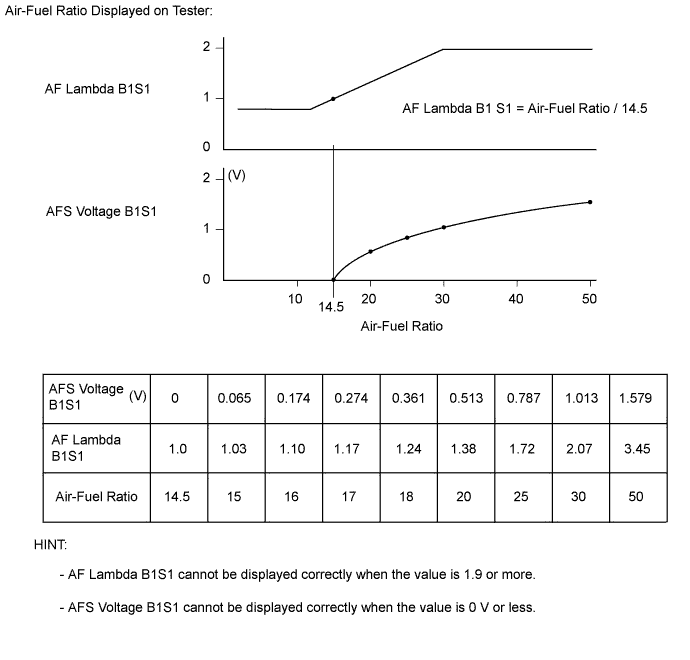
AFS Voltage B1S1 Data List Normal Data List Values Faulty Component Diagnosis Note AFS Voltage B1S1 - -
-
Check the air fuel ratio sensor output with the exhaust gas temperature (Exhaust Temperature B1S1) at 200°C (392°F) or higher (example: driving at speed of 50 km/h (31 mph) or more in 3rd gear).
-
If the exhaust fuel addition injector is clogged, even if DPNR catalyst regeneration is performed with the intelligent tester, the AFS voltage B1S1 value will not change.
Results of vehicle check:
-
Idling (warm up the engine): 1.32 V
-
Running without load (2500 rpm): 0.78 V
-
Running without load (5200 rpm): 1.22 V
-
Vehicle driven at constant speed of 50 km/h (31 mph) in 3rd gear: 1.24 V
-
Vehicle driven at constant speed of 50 km/h (31 mph) in 3rd gear during PM regeneration: 0.95 V
-
Driving with the accelerator fully open at 2000 rpm: 0.00 V
-
Driving with the accelerator fully open at 3000 rpm: 0.20 V
-
Driving with the accelerator fully open at 4000 rpm: 0.40 V
-
Driving with the accelerator fully open at 5000 rpm: 0.90 V
-
-
INSPECTION PROCEDURE
Note
-
After replacing the ECM, the new ECM requires registration Click here and initialization Click here.
-
After replacing a fuel supply pump, the ECM requires initialization Click here.
-
After replacing a fuel injector, the ECM requires registration Click here.
-
Explanation of Symptom
White Smoke When the engine is misfiring, any fuel that has been injected but remains unburned is exhausted as white smoke. Internal oil leak Click here
If oil leak occurs from turbine side seal, large amount of white smoke will be emitted from exhaust pipe.
Internal oil leak is not visible from outside of turbocharger.
PROCEDURE
-
CONFIRM CONDITIONS PRESENT WHEN WHITE SMOKE APPEARED WITH CUSTOMER
-
Ask the customer about the conditions when the white smoke was emitted.
- Driving conditions when the white smoke was generated.
- Is the white smoke constantly emitted, or only occasionally?
- Does the white smoke occur only when the vehicle is cold, or when the vehicle is both cold and hot?
- Is the white smoke emitted just after starting the vehicle only, or does it continue while the vehicle is idling?
-
Determine the symptoms of the problem to narrow down the possible causes.
NEXT 
-
-
READ OUTPUT DTC (RELATING TO ENGINE)
-
Connect the intelligent tester to the DLC3.
-
Turn the ignition switch to ON and turn the tester on.
-
Enter the following menus: Powertrain / Engine and ECT / DTC.
-
Read pending DTCs.
Result Result Proceed to No DTCs are output A Engine related DTCs are output B
B 
GO TO DTC CHART Click here
A
-
-
CHECK WHEN WHITE SMOKE IS EMITTED
-
Start the engine.
-
Fully depress the accelerator pedal and then release it.
-
Check whether the white smoke is emitted or not when racing the engine.
Note
Be sure not to check for white smoke indoors.
Tech Tips
-
If the white smoke is emitted only just after engine start and disappears later, the smoke is not from the turbocharger.
-
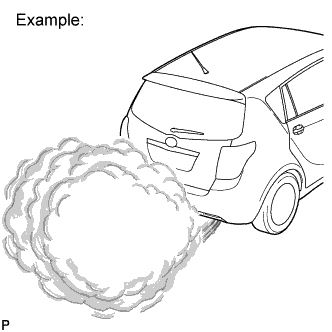
If the turbocharger is the cause of the problem, regardless of whether the engine is cold or warmed up, there will be a large amount of white smoke to the extent that visibility is obstructed for a few meters in the area of the smoke (as shown in the illustration).
-
Depending on whether there is oil mixed with the fuel, or whether there is unburned fuel present, the smell of the exhaust gas differs. When oil is mixed in, the exhaust gas smells like burning oil.
Result Result Proceed to White smoke is emitted just after engine start only A White smoke is always and continuously emitted B There is oil on the exhaust pipe etc.
Tech Tips
The oil on the exhaust pipe may be from the transmission, etc.
C Tech Tips
-
White smoke may be emitted at a specific exhaust gas temperature. Listed are possible symptoms and causes for this case. Please use this information as reference when carrying out malfunction diagnosis.
-
The exhaust gas temperature may be checked using "Exhaust Temperature B1S1, Exhaust Temperature B1S2" in the Data List.
Symptoms Causes White smoke emitted when the exhaust temperature is below 200°C (452°F) and the vehicle is traveling at low speed or when accelerating after decelerating.
-
Related Data List
- Exhaust Temperature B1S1
- Exhaust Temperature B1S2
When continuously traveling with the engine close to idle for 1 hour or more, such as when in heavy traffic, unburned fuel accumulates in the catalytic converter, and can produce white smoke when accelerating*.
*: In this case the white smoke is not caused by a defect, so explain to the customer that the white smoke is caused by an accumulation of unburned fuel due to low-speed driving etc., and monitor the situation.
(If the customer reports that the problem only occurs after continuous driving in heavy traffic/low speed driving, the problem may resolve itself when the catalytic converter temperature is raised through high-speed driving. However, if the catalytic converter activity is reduced, this will not resolve the problem, so the catalytic converter must be replaced. Deterioration of the catalytic converter can cause EGR malfunction and injector malfunction, so if there has not been any repair in the past, check and repair these components as well.)
White smoke is emitted when accelerating while the exhaust gas temperature is around 200 to 300°C (452 to 572°F) (in the process of rising to 500°C (932°F) for DPF regeneration).
-
Related Data List
- DPNR/DPF Status Reju (PM)
- Exhaust Temperature B1S1
- Exhaust Temperature B1S2
-
Deterioration of the exhaust gas temperature sensor may be causing the sensor to read lower than the actual temperature, so the amount of fuel added is increased and white smoke is produced. In this case the sensor will need to be replaced.
-
If catalytic converter activity has decreased, more fuel will be added without an increase in exhaust gas temperature, possibly resulting in white smoke.
In this case the catalytic converter needs to be replaced. Deterioration of the catalytic converter can cause EGR and injector malfunction, so if there has not been any repair in the past, check these components as well and repair if necessary.
Intermittent emission of white smoke that coincides with high catalytic converter temperature (500°C (932°F) or more) and rich air/fuel ratio (D-CAT only).
-
Related Data List
- AF Lambda B1S1
- AFS Voltage B1S1
- Exhaust Temperature B1S1
- Exhaust Temperature B1S2
White smoke is produced as the air/fuel ratio is too rich due to catalytic converter deterioration or characteristic deviation of the A/F sensor and MAF meter. -
B 
CHECK IDLING CONDITION Click here
C
CHECK FOR OIL LEAKAGE Click here
A
-
-
CHECK TEMPERATURE WHEN WHITE SMOKE IS EMITTED
-
Check whether the white smoke is emitted only when the engine coolant temperature is less than 0 °C (32°F).
Tech Tips
-
If so, the smoke is not from the turbocharger and may be the smoke of unburned fuel.
-
If misfiring occurs unburned fuel is emitted.
Result Result Proceed to White smoke is emitted when the temperature is less than (0 °C (32°F)) A White smoke is emitted irrespective of temperature B -
B
READ VALUE USING INTELLIGENT TESTER Click here
A
-
-
INSPECT GLOW PLUG RELAY
-
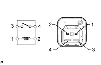
Remove the glow plug relay.
-
Measure the resistance of the relay.
Standard Resistance Tester Connection Condition Normal Value 3 - 4 When battery voltage is not applied to terminals 1 and 2 10 kΩ or higher 3 - 4 When battery voltage is applied to terminals 1 and 2 Below 1 Ω -
Reinstall the glow plug relay.
NG
REPLACE GLOW PLUG RELAY
OK
-
-
INSPECT GLOW PLUG ASSEMBLY (RESISTANCE)
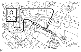
-
Disconnect the glow plug wire.
-
Measure the resistance according to the value(s) in the table below.
Standard Resistance Tester Connection Condition Normal Value Glow plug terminal - Body ground 20°C (68°F) Approximately 1.0 Ω Tech Tips
If any of the glow plugs have an open circuit, the engine power will be low only when the engine is cold.
Note
-
Take extreme care not to damage the glow plug pipes. Damaging them could cause an open circuit or shorten the life of the glow plugs.
-
Keep the glow plugs free of oil and fuel while cleaning.
-
Wipe any oil off of the terminal and Bakelite washer with a clean, dry cloth during inspection.
-
Do not apply higher than 11 V to the glow plugs as it may cause an open circuit.
-
NG
REPLACE GLOW PLUG ASSEMBLY Click here
OK
-
-
READ VALUE USING INTELLIGENT TESTER
-
Connect the intelligent tester to the DLC3.
-
Turn the ignition switch to ON and turn the tester on.
-
Start the engine
-
Enter the following menus: Powertrain / Engine and ECT / Data List / Fuel Press, Target Common Rail Pressure.
-
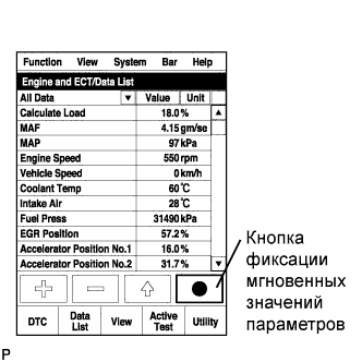
Take a snapshot with the intelligent tester.
Tech Tips
Detailed graphs can be displayed by transferring the stored snapshot from the tester to a PC (personal computer) with Intelligent Viewer installed.
-
Measure the difference between the target fuel pressure (Target Common Rail Pressure) and the actual fuel pressure (Fuel Press) when racing the engine with the accelerator pedal fully depressed.
OK The difference between the target fuel pressure and the actual fuel pressure is less than 10000 kPa. Tech Tips
-
"Target Common Rail Pressure" means target fuel pressure controlled by the ECM.
-
"Fuel Press" means actual fuel pressure.
-
NG
BLEED AIR FROM FUEL SYSTEM Click here
OK
-
-
CHECK FUEL INJECTOR COMPENSATION CODE
-
Read the fuel injector compensation codes Click here.
OK Compensation codes stored in the ECM match the compensation codes of the installed fuel injectors.
NG
REGISTER INJECTOR COMPENSATION CODE AND PERFORM PILOT QUANTITY LEARNING
OK
-
-
READ VALUE USING INTELLIGENT TESTER (INJECTION FEEDBACK VAL #1 TO #4, INJECTION VOLUME)
-
Check Injection Feedback Val #1 to #4 and Injection Volume in the snapshot taken after the engine is warmed up* and has been idling for 1 minute with the A/C off.
Tech Tips
Engine coolant temperature is 75°C (167°F) or higher.
Result Result Proceed to Injection Feedback Val #1 to #4 are 3 mm3/st or less and Injection Volume is 4.5 to 10 mm3/st
A Other than above B
A
CHECK EGR VALVE ASSEMBLY Click here
B
-
-
PERFORM ACTIVE TEST USING INTELLIGENT TESTER (CONTROL THE CYLINDER #1 TO #4 FUEL CUT)
Tech Tips
Use this Active Test to determine the malfunctioning cylinder.
-
Connect the intelligent tester to the DLC3.
-
Start the engine and turn the tester on.
-
Enter the following menus: Powertrain / Engine and ECT / Active Test / Control the Cylinder #1 to #4 Fuel Cut.
Tech Tips
If the engine idle speed does not change when a fuel injector is disabled, the cylinder being tested is malfunctioning. Record any malfunctioning cylinders.
NEXT
-
-
PERFORM ACTIVE TEST USING INTELLIGENT TESTER (CHECK THE CYLINDER COMPRESSION)
Tech Tips
Use this Active Test to help determine whether a cylinder has compression loss or not.
-
Connect the intelligent tester to the DLC3.
-
Turn the ignition switch to ON and turn the tester on.
-
Enter the following menus: Powertrain / Engine and ECT / Active Test / Check the Cylinder Compression / Data List / Compression / Engine Speed of Cyl #1 to #4.
-
Crank the engine.
-
Check the engine speed during the Active Test.
Result Result Proceed to The values of Engine Speed Cyl #1 to #4 are within +/-10 rpm of each other. A Other than above B Tech Tips
When cranking, if the speed of a cylinder is approximately 100 rpm more than the other cylinders, there is probably a complete loss of compression in that cylinder.
A
REPLACE FUEL INJECTOR OF MALFUNCTIONING CYLINDER Click here
B
-
-
CHECK CYLINDER COMPRESSION PRESSURE OF MALFUNCTIONING CYLINDER
Tech Tips
Measure the compression of the cylinder that had a high speed during the "Control the All Cylinders Fuel Cut" Active Test.
-
Check cylinder compression pressure Click here.
NG
CHECK ENGINE TO DETERMINE CAUSE OF LOW COMPRESSION
OK
-
-
REPLACE FUEL INJECTOR OF MALFUNCTIONING CYLINDER
Tech Tips
The injector is determined to be faulty as the corresponding cylinder is malfunctioning, but has no compression loss.
-
Replace the fuel injector of the malfunctioning cylinder Click here.
NEXT
-
-
BLEED AIR FROM FUEL SYSTEM
-
Bleed the air from the fuel system Click here.
NEXT
-
-
REGISTER INJECTOR COMPENSATION CODE AND PERFORM PILOT QUANTITY LEARNING
-
Register the injector compensation codes Click here.
-
Perform the fuel injector pilot quantity learning Click here.
NEXT
-
-
CONFIRM WHETHER MALFUNCTION HAS BEEN SUCCESSFULLY REPAIRED
-
Check whether the white smoke problem has been successfully repaired by starting the engine.
OK
REPLACE EGR VALVE ASSEMBLY Click here
NG
-
-
CHECK FUEL QUALITY
-
Check that only diesel fuel is being used.
-
Check that the fuel does not contain any impurities.
NEXT 
END
-
-
BLEED AIR FROM FUEL SYSTEM
-
Bleed the air from the fuel system Click here.
NEXT
-
-
CONFIRM WHETHER MALFUNCTION HAS BEEN SUCCESSFULLY REPAIRED
-
Check whether the white smoke problem has been successfully repaired by starting the engine.
OK
END
NG
-
-
CHECK IF FUEL IS BEING SUPPLIED TO FUEL SUPPLY PUMP
-
Disconnect the inlet hose from the fuel supply pump.
-
Operate the priming pump and check that fuel is being supplied to the fuel supply pump.
OK Fuel is properly supplied to the fuel supply pump when the priming pump is operated. Tech Tips
-
A lack of fuel causes the fuel pressure to drop.
-
Check that the fuel filter is not clogged
-
NEXT
-
-
CLEAN OR REPLACE FUEL FILTER
-
Clean the interior of the fuel filter case.
-
If the fuel filter is obviously dirty or clogged, replace the fuel filter.
NEXT
-
-
CHECK AND REPLACE CLOGGED FUEL PIPE (INCLUDING FUEL FREEZING) (FUEL TANK - FUEL SUPPLY PUMP)
-
Check and replace the clogged fuel pipe.
NEXT
-
-
BLEED AIR FROM FUEL SYSTEM
Tech Tips
If the fuel filter or fuel pipe has been replaced, be sure to remove any air in the system.
-
Bleed the air from the fuel system Click here
NEXT
-
-
CONFIRM WHETHER MALFUNCTION HAS BEEN SUCCESSFULLY REPAIRED
-
Check whether the white smoke problem has been successfully repaired by starting the engine.
NEXT
END
-
-
CHECK EGR VALVE ASSEMBLY
Tech Tips
-
If the amount of EGR is excessive due to a failure of the EGR valve, combustion when the coolant temperature is cold becomes unstable and leads to misfire.
-
When the EGR valve cannot completely close, a lack of power is felt and the MAF sensor value deviates from the standard value
-
Connect the intelligent tester to the DLC3.
-
Turn the ignition switch to ON and turn the tester on.
-
Enter the following menus: Powertrain / Engine and ECT / Data List / EGR Close Lrn. Status.
-
Read the value.
Standard EGR Close Lrn. Status is OK -
Enter the following menus: Powertrain / Engine and ECT / Active Test / Control the EGR Step Position.
-
When changing the Active Test value to 0, 30, 60, 90, 60, 30 and 0%, check that Actual EGR Valve Pos. smoothly changes to the set opening angle.
OK Value smoothly changes to set opening angle. -
Remove the EGR valve assembly Click here.
-
Visually check the EGR valve for deposits.
If there are deposits, clean the EGR valve.
Note
-
When cleaning the EGR valve, make sure the valve is completely closed.
-
Do not forcibly open the valve, as it may be damaged or deformed.
-
When cleaning the EGR valve, use a piece of cloth soaked with cleaning solvent. Spraying the solvent directly onto these parts or soaking the parts in the solvent may damage the parts.
-
-
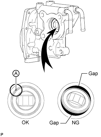
Hold the EGR valve up to a light, and then from the side indicated by the arrow in the illustration, visually check that there is no gap between the valve and body.
OK No light passes through (there is no gap between the valve and body). If light passes through (there is a gap between the valve and body), replace the EGR valve assembly.
Tech Tips
Light passes through part A shown in the illustration even if the valve is completely closed. This is not a problem.
NG
REPLACE EGR VALVE ASSEMBLY Click here
OK
-
-
CHECK ENGINE ASSEMBLY
-
Inspect the engine to see whether white smoke is being emitted due to defects in the engine itself.
-
Oil leaking into the combustion chamber due to a faulty valve stem oil seal.
-
Oil leaking into the combustion chamber due to a faulty injector nozzle sheet.
-
Low compression.
Tech Tips
If the engine runs too rough, Injection Feedback Val #1 to #4 cannot be corrected, and the readout will (incorrectly) show that Injection Feedback Val #1 to #4 are within the normal range.
Result If defects are found, repair and check that the symptoms are no longer present. -
NEXT
END
-
-
CHECK IDLING CONDITION
-
Start the engine.
-
Check the idling condition.
Result Result Proceed to There are problems such as rough idling or engine stall, and white smoke is emitted.
Tech Tips
If the pressure in the crank case has risen, white smoke will be produced just after the engine is started. In this case, if blow-by gas is ejected when the oil level gauge is slightly removed*, it is possible that the piston is damaged.
Note
*Do not completely remove the oil level gauge as oil may spray from the opening.
A Engine run smoothly at idle, however white smoke is emitted. B Tech Tips
It is possible to determine the faulty cylinder by carrying out the "Check the Cylinder Compression" of the Active Test.
A
REPAIR ENGINE ASSEMBLY
B
REPLACE TURBOCHARGER ASSEMBLY Click here
-
-
CHECK FOR OIL LEAKAGE
Tech Tips
For turbocharger oil leaks, see Turbo Charger Oil Leak and White Smoke Click here
-
Remove any oil in the exhaust pipe.
Tech Tips
Oil in the exhaust pipe is producing white smoke.
-
If there is an oil leak, repair the leak.
NEXT
END
-