СИСТЕМА ECD, Diagnostic DTC:P0340
| DTC Code | DTC Name |
|---|---|
| P0340 | Camshaft Position Sensor Circuit |
DESCRIPTION
The camshaft position sensor (G signal) consists of a magnet, iron core and pickup coil.
The G signal plate (timing sprocket) has one tooth on its outer circumference and is installed on the camshaft. When the camshaft rotates, the protrusion on the signal plate and the air gap on the pickup coil change, causing fluctuations in the magnetic field that generate a voltage in the pickup coil.
The NE signal plate has 34 teeth and is mounted on the crankshaft angle sensor plate. The NE signal sensor generates 34 signals for every revolution. The ECM detects the camshaft angle based on the G signal, and detects the crankshaft angle based on the NE signal.
| DTC Detection Drive Pattern | DTC Detection Condition | Trouble Area |
|---|---|---|
| Crank engine for 4 seconds or more (STA on) | STA on: No camshaft position sensor signal is sent to the ECM while cranking for 4 seconds or more. (2 trip detection logic) |
|
| Idle engine for 1 second or more (STA off) | STA off: Camshaft position sensor signal is not input with an engine speed of 650 rpm or more. (1 trip detection logic) |
|
| STA off: Phase deviation in crankshaft and camshaft position sensor signals with an engine speed of 650 to 3000 rpm occurs a certain number of times. (1 trip detection logic) |
Tech Tips
-
If DTC P0340 is stored, the following symptoms may appear:
-
Difficult starting
-
Misfire
-
Combustion noise
-
Black smoke
-
White smoke
-
Lack of power
WIRING DIAGRAM
Refer to DTC P0335 Click here.
INSPECTION PROCEDURE
Note
After replacing the ECM, the new ECM needs registration Click here and initialization Click here.
Tech Tips
-
After performing the inspection procedure for the crankshaft position sensor, if DTC P0340 is output again, check the following items related to the camshaft position sensor.
-
Installation condition of the crankshaft position sensor
-
No. 1 crankshaft position sensor plate
-
Connection of the crankshaft position sensor connector
-
Read freeze frame data using the intelligent tester. Freeze frame data records the engine condition when malfunctions are detected. When troubleshooting, freeze frame data can help determine if the vehicle was moving or stationary, if the engine was warmed up or not, and other data from the time the malfunction occurred.
PROCEDURE
-
INSPECT CAMSHAFT POSITION SENSOR
-
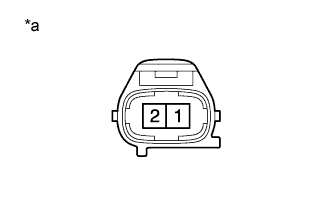
Text in Illustration *a Component without harness connected
(Camshaft Position Sensor)
Disconnect the camshaft position sensor connector.
-
Measure the resistance according to the value(s) in the table below.
Standard Resistance Tester Connection Condition Specified Condition 1 - 2 Cold 835 to 1400 Ω 1 - 2 Hot 1060 to 1645 Ω Tech Tips
In the table above, the terms "Cold" and "Hot" refer to the temperature of the coils in the sensor. "Cold" means approximately -10 to 50°C (14 to 122°F). "Hot" means approximately 50 to 100°C (122 to 212°F).
-
Reconnect the camshaft position sensor connector.
NG 
REPLACE CAMSHAFT POSITION SENSOR Click here
OK 
-
-
CHECK HARNESS AND CONNECTOR (CAMSHAFT POSITION SENSOR - ECM)
-
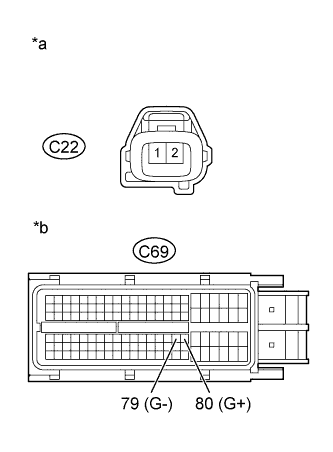
Text in Illustration *a Front view of wire harness connector
(to Camshaft Position Sensor)
*b Front view of wire harness connector
(to ECM)
Disconnect the camshaft position sensor connector.
-
Disconnect the ECM connector.
-
Measure the resistance according to the value(s) in the table below.
Standard Resistance (Check for Open) Tester Connection Condition Specified Condition C22-1 - C69-80 (G+) Always Below 1 Ω C22-2 - C69-79 (G-) Always Below 1 Ω Standard Resistance (Check for Short) Tester Connection Condition Specified Condition C22-1 or C69-80 (G+) - Body ground Always 10 kΩ or higher C22-2 or C69-79 (G-) - Body ground Always 10 kΩ or higher -
Reconnect the camshaft position sensor connector.
-
Reconnect the ECM connector.
NG
REPAIR OR REPLACE HARNESS OR CONNECTOR Click here
OK
-
-
CHECK CAMSHAFT POSITION SENSOR (SENSOR INSTALLATION)
-
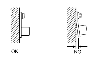
Check the sensor installation.
OK Sensor is installed correctly.
NG
SECURELY REINSTALL SENSOR Click here
OK
-
-
CHECK CAMSHAFT TIMING SPROCKET
-
Check the condition of the camshaft timing sprocket.
OK Camshaft timing sprocket does not have any cracks or deformation.
NG
REPLACE CAMSHAFT TIMING SPROCKET Click here
OK
-
-
CHECK HARNESS AND CONNECTOR (CRANKSHAFT POSITION SENSOR CIRCUIT)
-
Connect the intelligent tester to the DLC3.
-
Turn the engine switch on (IG).
-
Turn the tester on.
-
Clear the DTCs Click here.
-
Turn the engine switch off and wait for 30 seconds or more.
-
Start the engine and idle it for 4 seconds or more.
-
Turn the tester on.
-
Check the engine condition while wiggling the crankshaft position sensor wire harness for 4 seconds or more when idling.
-
Enter the following menus: Powertrain / Engine and ECT / DTC.
-
Read the DTCs.
Result Result Proceed to Except below A There are problem such as rough idle or engine stall when wire harness is wiggled, or DTC is output* B Tech Tips
*: As the DTC was stored due to a change in the contact resistance of the connector, repair or replace the wire harness or connector Click here.
B
CONFIRM WHETHER MALFUNCTION HAS BEEN SUCCESSFULLY REPAIRED Click here
A
-
-
REPLACE ECM
-
Replace the ECM Click here.
NEXT
CONFIRM WHETHER MALFUNCTION HAS BEEN SUCCESSFULLY REPAIRED Click here
-
-
REPLACE CAMSHAFT POSITION SENSOR
-
Replace the camshaft position sensor Click here.
NEXT
CONFIRM WHETHER MALFUNCTION HAS BEEN SUCCESSFULLY REPAIRED Click here
-
-
REPAIR OR REPLACE HARNESS OR CONNECTOR
-
Repair or replace the harness or connector.
NEXT
CONFIRM WHETHER MALFUNCTION HAS BEEN SUCCESSFULLY REPAIRED Click here
-
-
SECURELY REINSTALL SENSOR
-
Securely reinstall the sensor Click here.
NEXT
CONFIRM WHETHER MALFUNCTION HAS BEEN SUCCESSFULLY REPAIRED Click here
-
-
REPLACE CAMSHAFT TIMING SPROCKET
-
Replace the camshaft timing sprocket Click here.
NEXT
-
-
CONFIRM WHETHER MALFUNCTION HAS BEEN SUCCESSFULLY REPAIRED
-
Connect the intelligent tester to the DLC3.
-
Turn the engine switch on (IG).
-
Turn the tester on.
-
Clear the DTCs Click here.
-
Turn the engine switch off and wait for 30 seconds or more.
-
Start the engine and idle it for 4 seconds or more and turn the tester on.
-
Enter the following menus: Powertrain / Engine and ECT / DTC.
-
Confirm that the DTC is not output again.
NEXT 
END
-