СИСТЕМА ECD, Diagnostic DTC:P0234, P1251
| DTC Code | DTC Name |
|---|---|
| P0234 | Turbo / Super Charger Overboost Condition |
| P1251 | Step Motor for Turbocharger Control Circuit (Intermittent) |
DESCRIPTION
| DTC Detection Drive Pattern | DTC Detection Condition | Trouble Area |
|---|---|---|
| After warming up the engine, the vehicle is driven at a constant vehicle speed at an engine speed of 2400 rpm or more for 2 minutes | Actual turbocharger pressure "MAP" deviates by 30 kPa (225 mmHg, 8.9 in.Hg) or higher from the simulated target pressure "Target Booster Pressure" for 100 seconds at an engine speed of 2400 to 4000 rpm. (1 trip detection logic) |
|
| DTC Detection Drive Pattern | DTC Detection Condition | Trouble Area |
|---|---|---|
| After warming up the engine, fully depress the accelerator pedal for 5 seconds or more so that the engine speed is 2400 rpm or more. | The turbocharger pressure is 300 kPa (2250 mmHg, 89 in.Hg) or more for 5 seconds or more at an engine speed of 2000 to 4000 rpm. (1 trip detection logic) |
|
Tech Tips
If DTC P0234 or P1251 is stored, the following symptoms may appear.
-
When the nozzle vane of the turbocharger is stuck closed:
-
Vehicle surge when driving with full load
-
Low power output due to ECM limiting power output
| DTC No. | Data List |
|---|---|
| P0234 |
|
| P1251 |
WIRING DIAGRAM
Refer to DTC P0045 Click here.
INSPECTION PROCEDURE
Note
-
After replacing the ECM, the new ECM needs registration Click here and initialization Click here.
-
After replacing an injector assembly, the ECM needs registration Click here.
Tech Tips
Read freeze frame data using the intelligent tester. Freeze frame data records the engine condition when malfunctions are detected. When troubleshooting, freeze frame data can help determine if the vehicle was moving or stationary, if the engine was warmed up or not, and other data from the time the malfunction occurred.
PROCEDURE
-
READ OUTPUT DTC (RECORD STORED DTC AND FREEZE FRAME DATA)
-
Connect the intelligent tester to the DLC3.
-
Turn the engine switch on (IG) and turn the tester on.
-
Enter the following menus: Powertrain / Engine and ECT / DTC.
-
Record the stored DTC and Freeze Frame Data.
Tech Tips
Be sure to carefully examine "MAP" and "Target Booster Pressure" in the freeze frame data.
NEXT 
-
-
CHECK ANY OTHER DTCS OUTPUT (IN ADDITION TO DTC P0234 AND/OR P1251)
-
Connect the intelligent tester to the DLC3.
-
Turn the engine switch on (IG) and turn the tester on.
-
Enter the following menus: Powertrain / Engine and ECT / DTC.
-
Read the DTCs.
Result Result Proceed to DTC P0234 and/or P1251 are output A DTC P0234 and/or P1251 and other DTCs are output B Tech Tips
If DTCs other than P0234 and/or P1251 are output, perform troubleshooting for those DTCs first.
B 
GO TO DTC CHART Click here
A
-
-
READ VALUE USING INTELLIGENT TESTER (MAP AND TARGET BOOSTER PRESSURE)
-
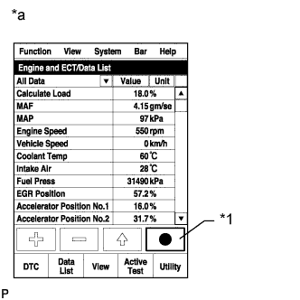
Text in Illustration *1 Snapshot Button *a Reference Connect the intelligent tester to the DLC3.
-
Start the engine and turn the tester on.
-
Enter the following menus: Powertrain / Engine and ECT / Data List / MAP and Target Booster Pressure.
-
Take a snapshot when the engine speed is maintained at 4500 rpm with no load.
-
Read the values of "MAP" and "Target Booster Pressure" in the Data List using the snapshot review function.
Result Result Proceed to Difference between MAP and Target Booster Pressure is +/-15 kPa or higher A Except above B
B 
CONFIRM WHETHER MALFUNCTION HAS BEEN SUCCESSFULLY REPAIRED Click here
A
-
-
CHECK AIR INTAKE SYSTEM
-
Check for air leaks and blockages between the air cleaner case and turbocharger sub-assembly, and between turbocharger sub-assembly and intake manifold.
Result Result Proceed to Leaks and/or blockages exist in the intake system A No leaks and/or blockages in the intake system B Tech Tips
-
Inspect the air intake system, especially hoses and pipes between the air cleaner assembly and turbocharger sub-assembly.
-
Check for abnormal disconnections, pipe and hose squashing, and any damage in the intake system.
-
Using your hand, check whether the pipes and hoses in the intake system are securely connected.
-
By applying soapy water and revving up the engine, air leaks from the intake system can be checked by checking for bubbles.
-
Check for any modifications in the intake system made by the user.
-
Check if the vacuum hose for the manifold absolute pressure sensor is disconnected.
-
B
CHECK CONNECTION OF VACUUM HOSE Click here
A
-
-
REPAIR OR REPLACE AIR INTAKE SYSTEM
NEXT
-
READ VALUE USING INTELLIGENT TESTER (MAP AND TARGET BOOSTER PRESSURE)
-
Text in Illustration *1 Snapshot Button *a Reference Connect the intelligent tester to the DLC3.
-
Start the engine and turn the tester on.
-
Enter the following menus: Powertrain / Engine and ECT / Data List / MAP and Target Booster Pressure.
-
Take a snapshot when the engine speed is maintained at 4500 rpm with no load.
-
Read the values of "MAP" and "Target Booster Pressure" in the Data List using the snapshot review function.
Result Result Proceed to Difference between MAP and Target Booster Pressure is +/-15 kPa or higher A Except above B
B
CONFIRM WHETHER MALFUNCTION HAS BEEN SUCCESSFULLY REPAIRED Click here
A
-
-
CHECK CONNECTION OF VACUUM HOSE
-
Check the turbocharger system vacuum hose connections
NG
REPAIR OR REPLACE VACUUM HOSE Click here
OK
-
-
INSPECT VACUUM REGULATING VALVE ASSEMBLY (FOR TURBOCHARGER CONTROL)
-
Inspect the vacuum regulating valve assembly (for turbocharger control) Click here.
NG
REPLACE VACUUM REGULATING VALVE ASSEMBLY (FOR TURBOCHARGER CONTROL) Click here
OK
-
-
CHECK TURBOCHARGER SUB-ASSEMBLY
-
Check the turbocharger sub-assembly Click here.
NG
REPLACE TURBOCHARGER SUB-ASSEMBLY Click here
OK
-
-
CHECK HARNESS AND CONNECTOR (VACUUM REGULATING VALVE ASSEMBLY - ECM)
-
Disconnect the vacuum regulating valve assembly (for turbocharger control) connector.
-
Disconnect the ECM connector.
-
Measure the resistance according to the value(s) in the table below.
Standard Resistance (Check for Open) Tester Connection Condition Specified Condition C56-2 (EGR) - C69-83 (VN) Always Below 1 Ω Standard Resistance (Check for Short) Tester Connection Condition Specified Condition C56-2 (EGR) or C69-83 (VN) - Body ground Always 10 kΩ or higher -
Reconnect the vacuum regulating valve assembly (for turbocharger control) connector.
-
Reconnect the ECM connector.
NG
REPAIR OR REPLACE HARNESS OR CONNECTOR Click here
OK
-
-
CHECK DIESEL THROTTLE BODY ASSEMBLY
-
Text in Illustration *1 Snapshot Button *a Reference Connect the intelligent tester to the DLC3.
-
Start the engine and turn the tester on.
-
Enter the following menus: Powertrain / Engine and ECT / Data List / Actual Throttle Position.
-
Take a snapshot when accelerating with the accelerator fully depressed.
-
Read the value of "Actual Throttle Position" in the Data List using the snapshot review function.
Result The value for "Actual Throttle Position" is 0%.
NG
REPLACE DIESEL THROTTLE BODY ASSEMBLY Click here
OK
-
-
CHECK ELECTRIC EGR CONTROL VALVE ASSEMBLY
-
Text in Illustration *1 Snapshot Button *a Reference Connect the intelligent tester to the DLC3.
-
Start the engine and turn the tester on.
-
Enter the following menus: Powertrain / Engine and ECT / Data List / Actual EGR Valve Pos.
-
Take a snapshot when accelerating with the accelerator fully depressed.
-
Read the value of "Actual EGR Valve Pos." in the Data List using the snapshot review function.
Result The value for "Actual EGR Valve Pos." is 0%.
NG
REPLACE ELECTRIC EGR CONTROL VALVE ASSEMBLY Click here
OK
-
-
PERFORM ACTIVE TEST USING INTELLIGENT TESTER (ACTIVATE THE VSV FOR EGR COOLER BYPASS)
-
Connect the intelligent tester to the DLC3.
-
Start the engine and warm it up, and make sure the A/C switch and all accessory switches are off.
-
Turn the ignition switch off and wait for 30 seconds.
-
Start the engine and turn the tester on.
-
Enter the following menus: Powertrain / Engine and ECT / Data List / MAF.
-
Read the MAF value displayed on the tester while the engine is idling.
-
Enter the following menus: Powertrain / Engine and ECT / Active Test / Activate the VSV for EGR Cooler Bypass / Data List / EGR Cooler Bypass Position.
Tech Tips
Whether the EGR is passing through the bypass side or cooler side during the Active Test can be confirmed by checking EGR Cooler Bypass Position.
-
Using the Active Test function, switch the EGR valve bypass switching valve between "Cooler" and "Bypass" a few times, and then check whether the MAF value changes after switching the valve from "Cooler" to "Bypass".
Tech Tips
If idling continues for 20 minutes or more, the EGR valve target opening angle becomes 0% (EGR valve fully closed). As this makes diagnosis impossible, it becomes necessary to drive the vehicle or restart the engine.
Result Tester Display Result Proceed to Activate the VSV for EGR Cooler Bypass:
Cooler to Bypass
MAF value does not change A MAF value changes B Tech Tips
If the EGR cooler is clogged, the mass air flow changes.
B
REPLACE EGR WITH COOLER PIPE SUB-ASSEMBLY Click here
A
-
-
READ VALUE USING INTELLIGENT TESTER (INJECTION FEEDBACK VAL #1 TO #4)
-
Connect the intelligent tester to the DLC3.
-
Turn the engine switch on (IG) and turn the tester on.
-
Start the engine and warm it up.
-
Enter the following menus: Powertrain / Engine and ECT / Data List / Injection Feedback Val #1 to #4.
-
Read the values.
Standard Value Item Engine Speed* Reference Value Injection Feedback Val #1 to #4 Idling -3.0 to 3.0 mm3/st
Tech Tips
-
*: The A/C switch and all accessory switches should be off, and the engine should be fully warmed up.
-
When the values are outside the standard range, deposits inside the injector assemblies may be causing the problem.
OK Values are within the standard range. -
NG
REPLACE INJECTOR ASSEMBLY OF MALFUNCTIONING CYLINDER Click here
OK
-
-
CHECK ANY OTHER DTCS OUTPUT (IN ADDITION TO DTC P0234 AND/OR P1251)
-
Connect the intelligent tester to the DLC3.
-
Turn the engine switch on (IG).
-
Turn the tester on.
-
Clear the DTCs Click here.
-
Turn the engine switch off and wait for 30 seconds or more.
-
Start the engine and warm it up for 1 minute or more.
-
Turn the tester on.
-
Read the value of Engine Speed from the Freeze Frame Data recorded previously.
Tech Tips
When performing the DTC detection drive pattern, make sure the engine speed increases to 2400 rpm or more and exceeds the "Engine Speed" value from the freeze frame data.
-
After warming up the engine, drive the vehicle at a constant vehicle speed at an engine speed of 2400 rpm or more for 2 minutes.
-
With the engine warmed up, fully depress the accelerator pedal for 5 seconds or more so that the engine speed is 2400 rpm or more.
-
Enter the following menus: Powertrain / Engine and ECT / DTC / Pending.
-
Read the DTC.
Result Result Proceed to DTC is not output A DTC P0234 and/or P1251 is output B
B
REPLACE ECM Click here
A 
END
-
-
REPLACE INJECTOR ASSEMBLY OF MALFUNCTIONING CYLINDER
-
Replace the injector assembly Click here.
Note
-
When replacing the injector assembly for a cylinder, always be sure to use a new injection pipe.
-
Follow the procedure in the repair manual and temporarily install the injection pipes and nozzle leakage pipe, and then correctly position the injector assemblies. After that, tighten parts according to the torque specifications.
-
If the installation procedure is not performed correctly, injector assemblies may become out of position, which may cause the injector assemblies to deteriorate, resulting in malfunctions.
-
If an injector assembly deteriorates and malfunctions, other problems such as knocking, rough idle, etc. may occur.
-
If an injector assembly becomes out of position, it is possible that the seal between the injector assembly and injection pipe may become incomplete, resulting in a fuel leak.
-
NEXT
-
-
BLEED AIR FROM FUEL SYSTEM
-
Bleed the air from the fuel system Click here.
NEXT
-
-
REGISTER INJECTOR COMPENSATION CODE AND PERFORM PILOT QUANTITY LEARNING
-
Register the injector compensation code Click here.
-
Perform the injector pilot quantity learning Click here.
NEXT
CONFIRM WHETHER MALFUNCTION HAS BEEN SUCCESSFULLY REPAIRED Click here
-
-
REPAIR OR REPLACE VACUUM HOSE
-
Repair or replace the vacuum hose.
NEXT
CONFIRM WHETHER MALFUNCTION HAS BEEN SUCCESSFULLY REPAIRED Click here
-
-
REPLACE VACUUM REGULATING VALVE ASSEMBLY (FOR TURBOCHARGER CONTROL)
-
Replace the vacuum regulating valve assembly (for turbocharger control) Click here.
NEXT
CONFIRM WHETHER MALFUNCTION HAS BEEN SUCCESSFULLY REPAIRED Click here
-
-
REPLACE TURBOCHARGER SUB-ASSEMBLY
-
Replace the turbocharger sub-assembly Click here.
NEXT
CONFIRM WHETHER MALFUNCTION HAS BEEN SUCCESSFULLY REPAIRED Click here
-
-
REPAIR OR REPLACE HARNESS OR CONNECTOR
-
Repair or replace the harness or connector.
NEXT
CONFIRM WHETHER MALFUNCTION HAS BEEN SUCCESSFULLY REPAIRED Click here
-
-
REPLACE DIESEL THROTTLE BODY ASSEMBLY
-
Replace the diesel throttle body assembly Click here.
NEXT
CONFIRM WHETHER MALFUNCTION HAS BEEN SUCCESSFULLY REPAIRED Click here
-
-
REPLACE ELECTRIC EGR CONTROL VALVE ASSEMBLY
-
Replace the electric EGR control valve assembly Click here.
NEXT
CONFIRM WHETHER MALFUNCTION HAS BEEN SUCCESSFULLY REPAIRED Click here
-
-
REPLACE EGR WITH COOLER PIPE SUB-ASSEMBLY
-
Replace the EGR with cooler pipe sub-assembly Click here.
NEXT
CONFIRM WHETHER MALFUNCTION HAS BEEN SUCCESSFULLY REPAIRED Click here
-
-
REPLACE ECM
-
Replace the ECM Click here.
NEXT
-
-
CONFIRM WHETHER MALFUNCTION HAS BEEN SUCCESSFULLY REPAIRED
-
Connect the intelligent tester to the DLC3.
-
Turn the engine switch on (IG).
-
Turn the tester on.
-
Clear the DTCs Click here.
-
Turn the engine switch off and wait for 30 seconds or more.
-
Start the engine and warm it up.
-
Turn the tester on.
-
Read the value of Engine Speed from the Freeze Frame Data recorded previously.
Tech Tips
When performing the DTC detection drive pattern, make sure the engine speed increases to 2400 rpm or more and exceeds the "Engine Speed" value from the freeze frame data.
-
After warming up the engine, drive the vehicle at a constant vehicle speed at an engine speed of 2400 rpm or more for 2 minutes [A].
-
With the engine warmed up, fully depress the accelerator pedal for 5 seconds or more so that the engine speed is 2400 rpm or more [B].
-
Confirm that the DTC is not output again.
Tech Tips
Perform the following procedure using the tester to determine whether or not the DTC judgment has been carried out.
-
Enter the following menus: Powertrain / Engine and ECT / Utility / All Readiness.
-
Input DTC P0234 or P1251.
-
Check that STATUS is NORMAL.
Tech Tips
-
If STATUS is NORMAL, DTC judgment is complete and the system is determined to be normal.
-
If STATUS is INCOMPLETE or N/A, perform [A] and [B] again.
-
-
NEXT
END
-