СИСТЕМА ECD, Diagnostic DTC:P0107, P0108
| DTC Code | DTC Name |
|---|---|
| P0107 | Manifold Absolute Pressure / Barometric Pressure Circuit Low Input |
| P0108 | Manifold Absolute Pressure / Barometric Pressure Circuit High Input |
DESCRIPTION
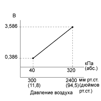
The manifold absolute pressure sensor detects the intake manifold pressure. The ECM determines the basic injection volume and injection advance timing based on the voltage output by the manifold absolute pressure sensor.
The manifold absolute pressure sensor monitors the absolute pressure inside the intake manifold (default is 0 kPa [0 mmHg, 0 in.Hg]). As a result the ECM controls the air-fuel ratio at the proper level under any driving conditions.
| DTC Detection Drive Pattern | DTC Detection Condition | Trouble Area |
|---|---|---|
| After engine is started for 2 seconds, race engine for 1 second | After the engine is started, condition (a) continues for more than 0.5 seconds (1 trip detection logic): (a) Manifold absolute pressure sensor voltage is 0.1 V or less. |
|
| DTC Detection Drive Pattern | DTC Detection Condition | Trouble Area |
|---|---|---|
| After engine is started for 2 seconds, race engine for 1 second | After the engine is started, condition (a) continues for more than 0.5 seconds (1 trip detection logic): (a) Manifold absolute pressure sensor voltage is 4.8 V or higher. |
|
| DTC No. | Data List |
|---|---|
| P0107 |
|
| P0108 |
Tech Tips
-
If DTC P0107 and/or P0108 is stored, the following symptoms may appear:
-
Misfire
-
Combustion noise
-
Black smoke
-
White smoke
-
Lack of power
-
When DTC P0107 or P0108 is stored, check the intake manifold pressure by entering the following menus: Powertrain / Engine and ECT / Data List / MAP.
Reference Intake Manifold Pressure Malfunction Approximately 0 kPa
-
Open in VC circuit
-
Short in PIM circuit
250 kPa (1875 mmHg, 73.8 in.Hg) or higher
-
Open in PIM circuit
-
Open in E2 circuit
-
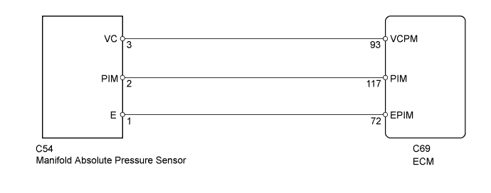
WIRING DIAGRAM
INSPECTION PROCEDURE
Note
After replacing the ECM, the new ECM needs registration Click here and initialization Click here.
Tech Tips
-
If DTCs relating to different systems are stored and they share terminal E2 as their ground, check this ground circuit first.
-
Read freeze frame data using the intelligent tester. Freeze frame data records the engine condition when malfunctions are detected. When troubleshooting, freeze frame data can help determine if the vehicle was moving or stationary, if the engine was warmed up or not, and other data from the time the malfunction occurred.
PROCEDURE
-
READ VALUE USING INTELLIGENT TESTER (MANIFOLD ABSOLUTE PRESSURE)
-
Connect the intelligent tester to the DLC3.
-
Turn the ignition switch to ON and turn the tester on.
-
Enter the following menus: Powertrain / Engine and ECT / Data List / MAP.
-
Read the value.
OK Same value as the actual atmospheric pressure. Tech Tips
-
Standard atmospheric pressure is 101 kPa. For every 100 m increase in altitude, pressure drops by 1 kPa. Varies by weather (high atmospheric pressure, low atmospheric pressure).
-
Also, check "Atmosphere Pressure" in the Data List.
-
OK 
CONFIRM WHETHER MALFUNCTION HAS BEEN SUCCESSFULLY REPAIRED Click here
NG
CHECK HARNESS AND CONNECTOR (MANIFOLD ABSOLUTE PRESSURE SENSOR - ECM) Click here
-
-
CHECK HARNESS AND CONNECTOR (MANIFOLD ABSOLUTE PRESSURE SENSOR - ECM)
-
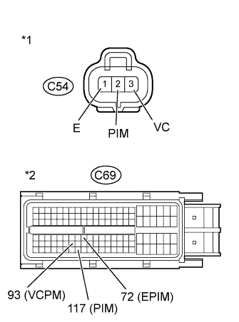
Text in Illustration *1 Front view of wire harness connector
(to Absolute Pressure Sensor)
*2 Front view of wire harness connector
(to ECM)
Disconnect the manifold absolute pressure sensor connector.
-
Disconnect the ECM connector.
-
Measure the resistance according to the value(s) in the table below.
Standard Resistance (Check for Open) Tester Connection Condition Specified Condition C54-2 (PIM) - C69-117 (PIM) Always Below 1 Ω C54-3 (VC) - C69-93 (VCPM) Always Below 1 Ω C54-1 (E) - C69-72 (EPIM) Always Below 1 Ω Standard Resistance (Check for Short) Tester Connection Condition Specified Condition C54-2 (PIM) or C69-117 (PIM) - Body ground Always 10 kΩ or higher C54-3 (VC) or C69-93 (VCPM) - Body ground Always 10 kΩ or higher -
Reconnect the manifold absolute pressure sensor connector.
-
Reconnect the ECM connector.
NG
REPAIR OR REPLACE HARNESS OR CONNECTOR Click here
OK 
-
-
CHECK ECM TERMINAL VOLTAGE (VC TERMINAL)
-
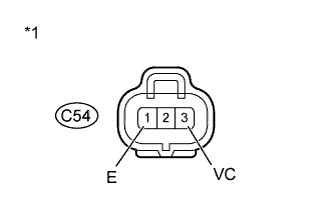
Text in Illustration *1 Front view of wire harness connector
(to Absolute Pressure Sensor)
Disconnect the manifold absolute pressure sensor connector.
-
Measure the voltage according to the value(s) in the table below.
Standard Voltage Tester Connection Switch Condition Specified Condition C54-3 (VC) - C54-1 (E) Ignition switch ON 4.5 to 5.5 V -
Reconnect the manifold absolute pressure sensor connector.
NG
REPLACE ECM Click here
OK
-
-
REPLACE MANIFOLD ABSOLUTE PRESSURE SENSOR
-
Replace the manifold absolute pressure sensor Click here.
NEXT
-
-
CHECK WHETHER DTC OUTPUT RECURS
-
Connect the intelligent tester to the DLC3.
-
Clear the DTCs Click here.
-
Turn the ignition switch off for 30 seconds or more.
-
Turn the tester off.
-
Start the engine.
-
After the engine is started for 2 seconds, race the engine for 1 second.
-
Turn the tester on.
-
Confirm that the DTC is not output again.
-
Enter the following menus: Powertrain / Engine and ECT / Utility / All Readiness.
-
Input DTC P0107 or P0108.
-
Check the DTC judgment result.
Result Result Proceed to ABNORMAL A NORMAL B Tech Tips
If STATUS is INCOMPLETE or UNKNOWN, race the engine for 1 minute, and then idle the engine for 5 minutes.
B 
END
A
-
-
REPLACE ECM
-
Replace the ECM Click here.
NEXT
CONFIRM WHETHER MALFUNCTION HAS BEEN SUCCESSFULLY REPAIRED Click here
-
-
REPAIR OR REPLACE HARNESS OR CONNECTOR
-
Repair or replace the harness or connector.
NEXT
-
-
CONFIRM WHETHER MALFUNCTION HAS BEEN SUCCESSFULLY REPAIRED
-
Connect the intelligent tester to the DLC3.
-
Clear the DTCs Click here.
-
Turn the ignition switch off for 30 seconds or more.
-
Turn the tester off.
-
Turn the ignition switch to ON for 3 seconds and turn the tester on.
-
After the engine is started for 2 seconds, race the engine for 1 second.
-
Confirm that the DTC is not output again.
Tech Tips
Perform the following procedure using the tester to determine whether or not the DTC judgment has been carried out.
-
Enter the following menus: Powertrain / Engine and ECT / Utility / All Readiness.
-
Input DTC P0107 or P0108.
-
Check that STATUS is NORMAL. If STATUS is INCOMPLETE or UNKNOWN, race the engine for 1 minute and then idle the engine for 5 minutes.
-
NEXT 
END
-