СИСТЕМА ECD (для DPF) VC Output Circuit
DESCRIPTION
The ECM constantly generates 5 V of power from the battery voltage supplied to the +B (BATT) terminal to operate the microprocessor. The ECM also provides this power to the sensors through the VC output circuit.
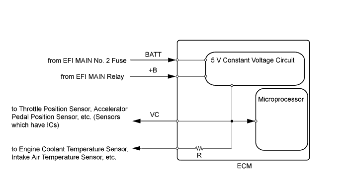
When the VC circuit is short-circuited, the microprocessor in the ECM and sensors that are supplied with power through the VC circuit are inactivated because the power is not supplied from the VC circuit. Under this condition, the system does not start up and the MIL does not illuminate even if the system malfunctions.
Tech Tips
Under normal conditions, the MIL is illuminated for several seconds when the ignition switch is first turned ON. The MIL goes off when the engine is started.
WIRING DIAGRAM
INSPECTION PROCEDURE
Note
After replacing the ECM, the new ECM needs registration Click here and initialization Click here.
PROCEDURE
-
CHECK MIL
-
Check that the Malfunction Indicator Lamp (MIL) lights up when turning the ignition switch to ON.
Result Result Proceed to MIL illuminates A MIL does not illuminate B
A 
END
B 
-
-
CHECK COMMUNICATION BETWEEN INTELLIGENT TESTER AND ECM
-
Connect the intelligent tester to the DLC3.
-
Turn the ignition switch to ON and tester on.
-
Check the communication between the tester and ECM.
Result Result Proceed to Communication is possible A Communication is not possible B
A
GO TO MIL CIRCUIT Click here
B
-
-
CHECK MIL (ACCELERATOR PEDAL POSITION SENSOR)
-
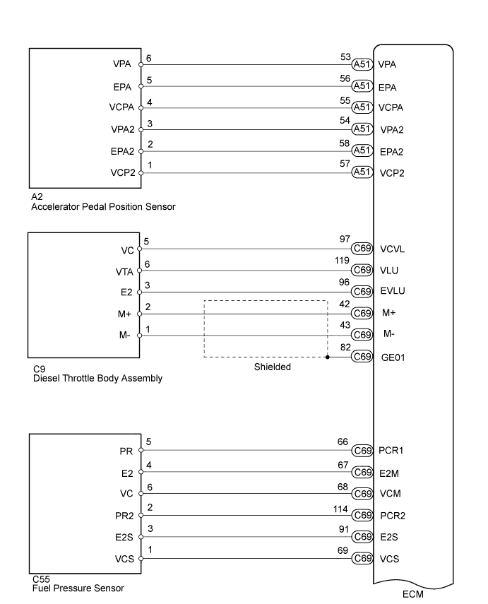
Disconnect the accelerator pedal position sensor connector.
-
Turn the ignition switch to ON.
-
Check the MIL.
Result Result Proceed to MIL illuminates A MIL does not illuminate B -
Reconnect the accelerator pedal position sensor connector.
A
REPLACE ACCELERATOR PEDAL ROD ASSEMBLY Click here
B
-
-
CHECK MIL (DIESEL THROTTLE BODY ASSEMBLY)
-
Disconnect the diesel throttle body assembly connector.
-
Turn the ignition switch to ON.
-
Check the MIL.
Result Result Proceed to MIL illuminates A MIL does not illuminate B -
Reconnect the diesel throttle body assembly connector.
A
REPLACE DIESEL THROTTLE BODY ASSEMBLY Click here
B
-
-
CHECK MIL (FUEL PRESSURE SENSOR)
-
Disconnect the fuel pressure sensor connector.
-
Turn the ignition switch to ON.
-
Check the MIL.
Result Result Proceed to MIL illuminates A MIL does not illuminate B -
Reconnect the fuel pressure sensor connector.
A
REPLACE COMMON RAIL Click here
B
-
-
CHECK MIL (EGR VALVE ASSEMBLY)
-
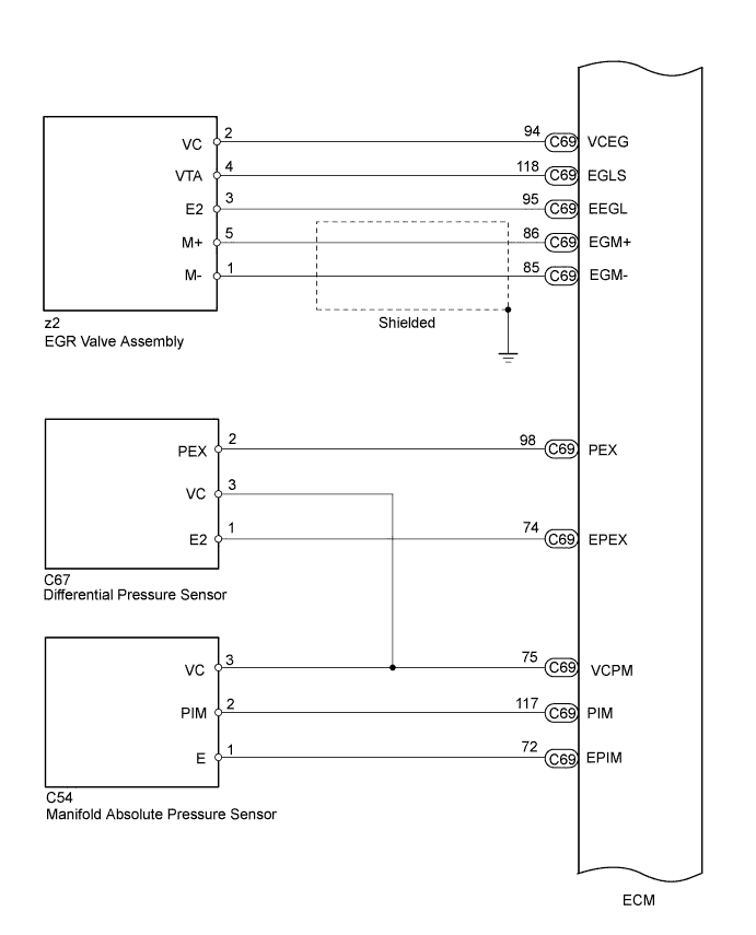
Disconnect the EGR valve assembly connector.
-
Turn the ignition switch to ON.
-
Check the MIL.
Result Result Proceed to MIL illuminates A MIL does not illuminate B -
Reconnect the EGR valve assembly connector.
A
REPLACE EGR VALVE ASSEMBLY Click here
B
-
-
CHECK MIL (DIFFERENTIAL PRESSURE SENSOR)
-
Disconnect the differential pressure sensor connector.
-
Turn the ignition switch to ON.
-
Check the MIL.
Result Result Proceed to MIL illuminates A MIL does not illuminate B -
Reconnect the differential pressure sensor connector.
A
REPLACE DIFFERENTIAL PRESSURE SENSOR Click here
B
-
-
CHECK MIL (MANIFOLD ABSOLUTE PRESSURE SENSOR)
-
Disconnect the manifold absolute pressure sensor connector.
-
Turn the ignition switch to ON.
-
Check the MIL.
Result Result Proceed to MIL illuminates A MIL does not illuminate B -
Reconnect the manifold absolute pressure sensor connector.
A
REPLACE MANIFOLD ABSOLUTE PRESSURE SENSOR Click here
B
-
-
CHECK MIL (CAMSHAFT POSITION SENSOR)
-
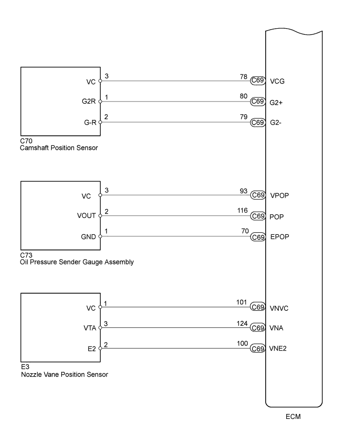
Disconnect the camshaft position sensor connector.
-
Turn the ignition switch to ON.
-
Check the MIL.
Result Result Proceed to MIL illuminates A MIL does not illuminate B -
Reconnect the camshaft position sensor connector.
A
REPLACE CAMSHAFT POSITION SENSOR Click here
B
-
-
CHECK MIL (OIL PRESSURE SENDER GAUGE ASSEMBLY)
-
Disconnect the oil pressure sender gauge assembly connector.
-
Turn the ignition switch to ON.
-
Check the MIL.
Result Result Proceed to MIL illuminates A MIL does not illuminate B -
Reconnect the oil pressure sender gauge assembly connector.
A
REPLACE OIL PRESSURE SENDER GAUGE ASSEMBLY Click here
B
-
-
CHECK MIL (NOZZLE VANE POSITION SENSOR)
-
Disconnect the nozzle vane position sensor connector.
-
Turn the ignition switch to ON.
-
Check the MIL.
Result Result Proceed to MIL illuminates A MIL does not illuminate B -
Reconnect the nozzle vane position sensor connector.
A
REPLACE TURBOCHARGER SUB-ASSEMBLY Click here
B
-
-
CHECK HARNESS AND CONNECTOR
-
Disconnect the accelerator pedal position sensor connector.
-
Disconnect the diesel throttle body assembly connector.
-
Disconnect the fuel pressure sensor connector.
-
Disconnect the EGR valve assembly connector.
-
Disconnect the differential pressure sensor connector.
-
Disconnect the manifold absolute pressure sensor connector.
-
Disconnect the camshaft position sensor connector.
-
Disconnect the oil pressure sender gauge assembly connector.
-
Disconnect the nozzle vane position sensor connector.
-
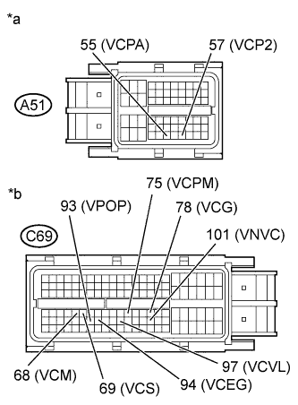
Text in Illustration *a Front view of wire harness connector
(to ECM)
*b Front view of wire harness connector
(to ECM)
Disconnect the ECM connectors.
-
Measure the resistance according to the value(s) in the table below.
Standard Resistance Tester Connection Condition Specified Condition A51-55 (VCPA) - Body ground Always 10 kΩ or higher A51-57 (VCP2) - Body ground Always 10 kΩ or higher C69-97 (VCVL) - Body ground Always 10 kΩ or higher C69-68 (VCM) - Body ground Always 10 kΩ or higher C69-69 (VCS) - Body ground Always 10 kΩ or higher C69-94 (VCEG) - Body ground Always 10 kΩ or higher C69-75 (VCPM) - Body ground Always 10 kΩ or higher C69-78 (VCG) - Body ground Always 10 kΩ or higher C69-93 (VPOP) - Body ground Always 10 kΩ or higher C69-101 (VNVC) - Body ground Always 10 kΩ or higher -
Reconnect the accelerator pedal position sensor connector.
-
Reconnect the diesel throttle body assembly connector.
-
Reconnect the fuel pressure sensor connector.
-
Reconnect the EGR valve assembly connector.
-
Reconnect the differential pressure sensor connector.
-
Reconnect the manifold absolute pressure sensor connector.
-
Reconnect the camshaft position sensor connector.
-
Reconnect the oil pressure sender gauge assembly connector.
-
Reconnect the nozzle vane position sensor connector.
-
Reconnect the ECM connectors.
NG
REPAIR OR REPLACE HARNESS OR CONNECTOR
OK 
REPLACE ECM Click here
-