| DTC Code | DTC Name |
|---|---|
| P2121 | Throttle / Pedal Position Sensor / Switch "D" Circuit Range / Performance |
DESCRIPTION
Refer to DTC P2120 (Click here).
| DTC Detection Drive Pattern | DTC Detection Condition | Trouble Area |
|---|---|---|
| Ignition switch ON
|
The difference between VPA and VPA2 is below 0.4 V, or higher than 1.2 V for 0.5 seconds. (1 trip detection logic) |
|
| DTC No. | Data List |
|---|---|
| P2121 |
|
INSPECTION PROCEDURE
After replacing the ECM, the new ECM needs registration (Click here) and initialization (Click here).
Read freeze frame data using the intelligent tester. Freeze frame data records the engine condition when malfunctions are detected. When troubleshooting, freeze frame data can help determine if the vehicle was moving or stationary, if the engine was warmed up or not, and other data from the time the malfunction occurred.
PROCEDURE
- Click here
READ VALUE USING INTELLIGENT TESTER (ACCELERATOR PEDAL POSITION SENSOR)
-
Connect the intelligent tester to the DLC3.
-
Turn the ignition switch to ON and turn the tester on.
-
Enter the following menus: Powertrain / Engine and ECT / Data List / Accel Sens. No.1 Volt % and Accel Sens. No.2 Volt %.
-
Read the values.
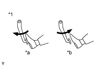
Standard Voltage Accelerator Pedal Accel Sens. No.1 Volt % Accel Sens. No.2 Volt % Released 8 to 28% 30 to 55% Depressed 51 to 86% 73 to 98% Table 3. Text in Illustration *1 Accelerator Pedal *a Depressed *b Released Table 4. Result Result Proceed to NG A OK B
-
- Click here
CHECK HARNESS AND CONNECTOR (ACCELERATOR PEDAL POSITION SENSOR - ECM)
-
Disconnect the accelerator pedal position sensor connector.
-
Disconnect the ECM connector.
-
Measure the resistance according to the value(s) in the table below.
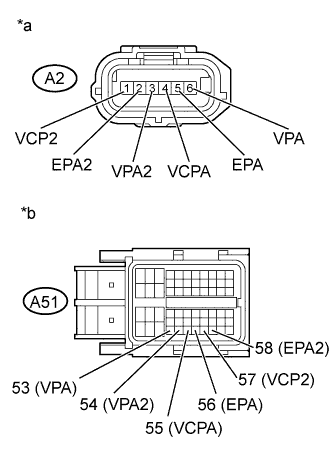
Standard Resistance Tester Connection Condition Specified Condition A2-1 (VCP2) - A51-57 (VCP2) Always Below 1 Ω A2-2 (EPA2) - A51-58 (EPA2) Always Below 1 Ω A2-3 (VPA2) - A51-54 (VPA2) Always Below 1 Ω A2-4 (VCPA) - A51-55 (VCPA) Always Below 1 Ω A2-5 (EPA) - A51-56 (EPA) Always Below 1 Ω A2-6 (VPA) - A51-53 (VPA) Always Below 1 Ω A2-1 (VCP2) or A51-57 (VCP2) - Body ground Always 10 kΩ or higher A2-2 (EPA2) or A51-58 (EPA2) - Body ground Always 10 kΩ or higher A2-3 (VPA2) or A51-54 (VPA2) - Body ground Always 10 kΩ or higher A2-4 (VCPA) or A51-55 (VCPA) - Body ground Always 10 kΩ or higher A2-5 (EPA) or A51-56 (EPA) - Body ground Always 10 kΩ or higher A2-6 (VPA) or A51-53 (VPA) - Body ground Always 10 kΩ or higher Table 5. Text in Illustration *a Front view of wire harness connector
(to Accelerator Pedal Position Sensor)
*b Front view of wire harness connector
(to ECM)
-
Reconnect the accelerator pedal position sensor connector.
-
Reconnect the ECM connector.
- OKClick here
- NGClick here
-
- Click here
REPLACE ACCELERATOR PEDAL ROD ASSEMBLY
-
Replace the accelerator pedal rod assembly (Click here).
- NEXTClick here
-
- Click here
CHECK WHETHER DTC OUTPUT RECURS (DTC P2121)
-
Connect the intelligent tester to the DLC3.
-
Clear the DTCs (Click here).
-
Turn the ignition switch to ON.
-
Fully close the accelerator pedal for 3 seconds or more, then hold it partway open for 3 seconds or more, and then fully open it for 3 seconds or more.
-
Enter the following menus: Powertrain / Engine and ECT / DTC.
-
Read the DTCs.
Table 6. Result Result Proceed to P2121 is output A No DTC is output B
-
- Click here
REPLACE ECM
-
Replace the ECM (Click here).
- NEXTClick here
-
- Click here
REPAIR OR REPLACE HARNESS OR CONNECTOR
-
Repair or replace the harness or connector.
- NEXTClick here
-
- Click here
CONFIRM WHETHER MALFUNCTION HAS BEEN SUCCESSFULLY REPAIRED
-
Connect the intelligent tester to the DLC3.
-
Clear the DTCs (Click here).
-
Turn the ignition switch to ON.
-
Fully close the accelerator pedal for 3 seconds or more, then hold it partway open for 3 seconds or more, and then fully open it for 3 seconds or more.
-
Enter the following menus: Powertrain / Engine and ECT / DTC.
-
Confirm that the DTC is not output again.
- NEXTClick here
-
- Click here
END