СИСТЕМА ECD (для CCo), Diagnostic DTC:P0627
| DTC Code | DTC Name |
|---|---|
| P0627 | Fuel Pump Control Circuit / Open |
DESCRIPTION
| DTC Detection Drive Pattern | DTC Detection Condition | Trouble Area |
|---|---|---|
| Idling for 1 second | Even though the CPU (command area inside ECU) is outputting the suction control valve operation duty, the output monitor signal is absent for 0.5 seconds. (1 trip detection logic) |
|
| DTC No. | Data List |
|---|---|
| P0627 | Fuel Press Target Common Rail Pressure |
Tech Tips
-
For more information on the fuel supply pump (suction control valve) and common rail system, refer to the System Description Click here.
-
When DTC P0627 is stored, check the internal fuel pressure of the common rail by entering the following menus on the intelligent tester: Powertrain / Engine and ECT / Data List / Fuel Press.
Under a stable operating condition such as idling, Fuel Press is within +/-5000 kPa of Target Common Rail Pressure.
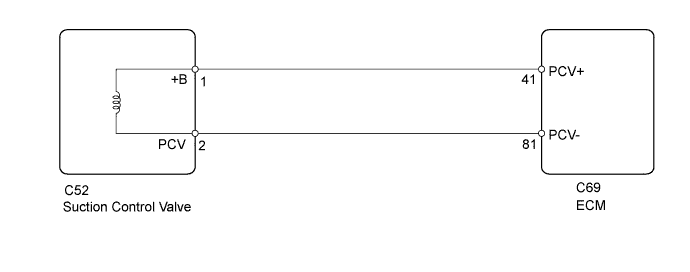
WIRING DIAGRAM
INSPECTION PROCEDURE
Note
-
After replacing the ECM, the new ECM needs registration Click here and initialization Click here.
-
After replacing the fuel supply pump, the ECM needs initialization Click here.
Tech Tips
Read freeze frame data using the intelligent tester. Freeze frame data records the engine condition when malfunctions are detected. When troubleshooting, freeze frame data can help determine if the vehicle was moving or stationary, if the engine was warmed up or not, and other data from the time the malfunction occurred.
PROCEDURE
-
INSPECT FUEL SUPPLY PUMP (SUCTION CONTROL VALVE)
-
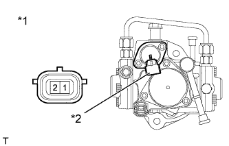
Text in Illustration *1 Fuel Supply Pump *2 Component without harness connected
(Suction Control Valve)
Disconnect the suction control valve connector.
-
Measure the resistance according to the value(s) in the table below.
Standard Resistance Tester Connection Condition Specified Condition 1 - 2 20°C (68°F) 1.9 to 2.3 Ω -
Reconnect the suction control valve connector.
NG 
REPLACE SUCTION CONTROL VALVE Click here
OK 
-
-
CHECK HARNESS AND CONNECTOR (SUCTION CONTROL VALVE - ECM)
-
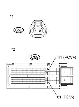
Text in Illustration *1 Front view of wire harness connector
(to Suction Control Valve)
*2 Front view of wire harness connector
(to ECM)
Disconnect the suction control valve connector.
-
Disconnect the ECM connector.
-
Measure the resistance according to the value(s) in the table below.
Standard Resistance (Check for Open) Tester Connection Condition Specified Condition C52-1 (+B) - C69-41 (PCV+) Always Below 1 Ω C52-2 (PCV) - C69-81 (PCV-) Always Below 1 Ω Standard Resistance (Check for Short) Tester Connection Condition Specified Condition C52-1 (+B) or C69-41 (PCV+) - Body ground Always 10 kΩ or higher C52-2 (PCV) or C69-81 (PCV-) - Body ground Always 10 kΩ or higher -
Reconnect the suction control valve connector.
-
Reconnect the ECM connector.
NG
REPAIR OR REPLACE HARNESS OR CONNECTOR Click here
OK
-
-
CHECK WHETHER DTC OUTPUT RECURS
-
Connect the intelligent tester to the DLC3
-
Turn the ignition switch to ON and turn the tester on.
-
Clear the DTCs Click here.
-
Start the engine and idle it for 1 second or more.
-
Enter the following menus: Powertrain / Engine and ECT / DTC.
-
Read the DTCs.
Result Result Proceed to No DTC is output A P0627 is output B
B
REPLACE ECM Click here
A 
END
-
-
REPLACE SUCTION CONTROL VALVE
-
Replace the suction control valve Click here.
NEXT
-
-
BLEED AIR FROM FUEL SYSTEM
-
Bleed the air from the fuel system Click here.
NEXT
-
-
PERFORM FUEL SUPPLY PUMP INITIALIZATION
-
Perform fuel supply pump initialization Click here.
NEXT
CONFIRM WHETHER MALFUNCTION HAS BEEN SUCCESSFULLY REPAIRED Click here
-
-
REPLACE ECM
-
Replace the ECM Click here.
NEXT
CONFIRM WHETHER MALFUNCTION HAS BEEN SUCCESSFULLY REPAIRED Click here
-
-
REPAIR OR REPLACE HARNESS OR CONNECTOR
-
Repair or replace the harness or connector.
NEXT
-
-
CONFIRM WHETHER MALFUNCTION HAS BEEN SUCCESSFULLY REPAIRED
-
Connect the intelligent tester to the DLC3.
-
Clear the DTCs Click here.
-
Turn the ignition switch off for 30 seconds or more.
-
Start the engine and idle it for 1 second or more.
-
Confirm that the DTC is not output again.
NEXT
END
-