СИСТЕМА ECD (для CCo), Diagnostic DTC:P0115, P0117, P0118
| DTC Code | DTC Name |
|---|---|
| P0115 | Engine Coolant Temperature Circuit |
| P0117 | Engine Coolant Temperature Circuit Low Input |
| P0118 | Engine Coolant Temperature Circuit High Input |
DESCRIPTION
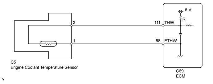
A thermistor is built into the Engine Coolant Temperature (ECT) sensor and it changes its resistance value according to the engine coolant temperature.
The structure of the sensor and connection to the ECM is the same as the intake air temperature sensor.
Tech Tips
If DTC P0115, P0117 or P0118 is stored, the ECM operates the fail-safe function in which the ECT is assumed to be 80°C (176°F).
| DTC Detection Drive Pattern | DTC Detection Condition | Trouble Area |
|---|---|---|
| Ignition switch ON for 0.5 seconds | Open or short in the engine coolant temperature (ECT) sensor circuit for 0.5 seconds. (1 trip detection logic) |
|
| DTC Detection Drive Pattern | DTC Detection Condition | Trouble Area |
|---|---|---|
| Ignition switch ON for 0.5 seconds | Short in the ECT sensor circuit for 0.5 seconds. (1 trip detection logic) |
|
| DTC Detection Drive Pattern | DTC Detection Condition | Trouble Area |
|---|---|---|
| Ignition switch ON for 0.5 seconds | Open in the ECT sensor circuit for 0.5 seconds. (1 trip detection logic) |
|
| DTC No. | Data List |
|---|---|
| P0115 | Coolant Temp |
| P0117 | |
| P0118 |
Tech Tips
-
If DTC P0115, P0117 and/or P0118 is stored, the following symptoms may appear:
-
Misfire
-
Combustion noise
-
Black smoke
-
White smoke
-
Lack of power
-
When DTC P0115, P0117 and/or P0118 is stored, check the engine coolant temperature by entering the following menus: Powertrain / Engine and ECT / Data List / Coolant Temp.
Reference: Temperature Displayed Malfunction -40°C (-40°F) Open circuit 140°C (284°F) or higher Short circuit
WIRING DIAGRAM
INSPECTION PROCEDURE
Note
After replacing the ECM, the new ECM needs registration Click here and initialization Click here.
Tech Tips
-
If DTCs relating to different systems are stored and they share terminal E2 as their ground, check this ground circuit first.
-
Read freeze frame data using the intelligent tester. Freeze frame data records the engine condition when malfunctions are detected. When troubleshooting, freeze frame data can help determine if the vehicle was moving or stationary, if the engine was warmed up or not, and other data from the time the malfunction occurred.
PROCEDURE
-
READ VALUE USING INTELLIGENT TESTER (ENGINE COOLANT TEMPERATURE)
-
Connect the intelligent tester to the DLC3.
-
Turn the ignition switch to ON and turn the tester on.
-
Enter the following menus: Powertrain / Engine and ECT / Data List / Coolant Temp.
-
Read the value.
OK 75 to 90°C (167 to 194°F) with warm engine. Result Result Proceed to -40°C (-40°F) A 140°C (284°F) or higher B 75 to 90°C (167 to 194°F) C Tech Tips
-
If there is an open circuit, the tester indicates -40°C (-40°F).
-
If there is a short circuit, the tester indicates 140°C (284°F) or more.
-
B 
READ VALUE USING INTELLIGENT TESTER (CHECK FOR SHORT IN WIRE HARNESS) Click here
C
CONFIRM WHETHER MALFUNCTION HAS BEEN SUCCESSFULLY REPAIRED Click here
A 
-
-
READ VALUE USING INTELLIGENT TESTER (CHECK FOR OPEN IN WIRE HARNESS)
-
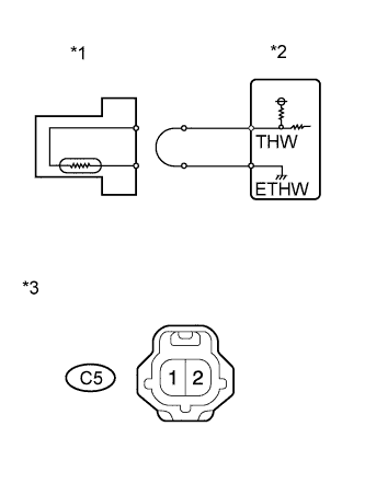
Text in Illustration *1 ECT Sensor *2 ECM *3 Front view of wire harness connector
(to ECT Sensor)
Disconnect the engine coolant temperature (ECT) sensor connector.
-
Connect terminals 1 and 2 of the ECT sensor wire harness side connector.
-
Connect the intelligent tester to the DLC3.
-
Turn the ignition switch to ON and turn the tester on.
-
Enter the following menus: Powertrain / Engine and ECT / Data List / Coolant Temp.
-
Read the value.
OK 140°C (284°F) or higher -
Reconnect the ECT sensor connector.
OK
CONFIRM GOOD CONNECTION TO SENSOR. IF OK, REPLACE ENGINE COOLANT TEMPERATURE SENSOR. Click here
NG
CHECK HARNESS AND CONNECTOR (ENGINE COOLANT TEMPERATURE SENSOR - ECM) Click here
-
-
CHECK HARNESS AND CONNECTOR (ENGINE COOLANT TEMPERATURE SENSOR - ECM)
-
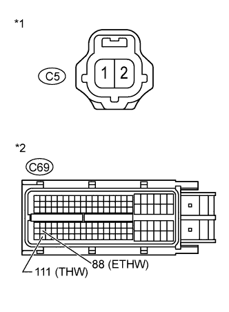
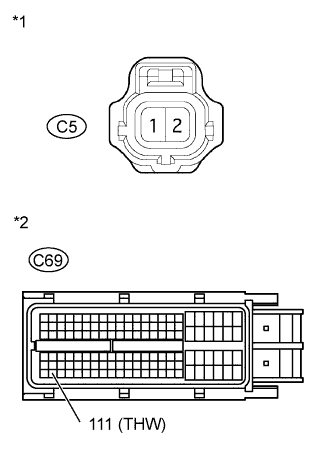
Text in Illustration *1 Front view of wire harness connector
(to ECT Sensor)
*2 Front view of wire harness connector
(to ECM)
Disconnect the ECT sensor connector.
-
Disconnect the ECM connector.
-
Measure the resistance according to the value(s) in the table below.
Standard Resistance Tester Connection Condition Specified Condition C5-2 - C69-111 (THW) Always Below 1 Ω C5-1 - C69-88 (ETHW) Always Below 1 Ω -
Reconnect the ECT sensor connector.
-
Reconnect the ECM connector.
OK
CONFIRM GOOD CONNECTION TO ECM. IF OK, REPLACE ECM. Click here
NG
REPAIR OR REPLACE HARNESS OR CONNECTOR Click here
-
-
READ VALUE USING INTELLIGENT TESTER (CHECK FOR SHORT IN WIRE HARNESS)
-
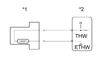
Text in Illustration *1 ECT Sensor *2 ECM Disconnect the ECT sensor connector.
-
Connect the intelligent tester to the DLC3.
-
Turn the ignition switch to ON and turn the tester on.
-
Enter the following menus: Powertrain / Engine and ECT / Data List / Coolant Temp.
-
Read the value.
OK -40°C (-40°F) -
Reconnect the ECT sensor connector.
OK
REPLACE ENGINE COOLANT TEMPERATURE SENSOR Click here
NG
CHECK HARNESS AND CONNECTOR (ENGINE COOLANT TEMPERATURE SENSOR - ECM) Click here
-
-
CHECK HARNESS AND CONNECTOR (ENGINE COOLANT TEMPERATURE SENSOR - ECM)
-
Text in Illustration *1 Front view of wire harness connector
(to ECT Sensor)
*2 Front view of wire harness connector
(to ECM)
Disconnect the ECT sensor connector.
-
Disconnect the ECM connector.
-
Measure the resistance according to the value(s) in the table below.
Standard Resistance Tester Connection Condition Specified Condition C5-2 or C69-111 (THW) - Body ground Always 10 kΩ or higher -
Reconnect the ECT sensor connector.
-
Reconnect the ECM connector.
NG
REPAIR OR REPLACE HARNESS OR CONNECTOR Click here
OK
-
-
REPLACE ECM
-
Replace the ECM Click here.
NEXT
CONFIRM WHETHER MALFUNCTION HAS BEEN SUCCESSFULLY REPAIRED Click here
-
-
CONFIRM GOOD CONNECTION TO SENSOR. IF OK, REPLACE ENGINE COOLANT TEMPERATURE SENSOR.
-
Replace the engine coolant temperature sensor Click here.
NEXT
CONFIRM WHETHER MALFUNCTION HAS BEEN SUCCESSFULLY REPAIRED Click here
-
-
REPAIR OR REPLACE HARNESS OR CONNECTOR
-
Repair or replace the harness or connector.
NEXT
CONFIRM WHETHER MALFUNCTION HAS BEEN SUCCESSFULLY REPAIRED Click here
-
-
CONFIRM GOOD CONNECTION TO ECM. IF OK, REPLACE ECM.
-
Replace the ECM Click here.
NEXT
CONFIRM WHETHER MALFUNCTION HAS BEEN SUCCESSFULLY REPAIRED Click here
-
-
REPLACE ENGINE COOLANT TEMPERATURE SENSOR
-
Replace the engine coolant temperature sensor Click here.
NEXT
-
-
CONFIRM WHETHER MALFUNCTION HAS BEEN SUCCESSFULLY REPAIRED
-
Connect the intelligent tester to the DLC3.
-
Clear the DTCs Click here.
-
Turn the ignition switch to ON for 1 second.
-
Enter the following menus: Powertrain / Engine and ECT / DTC.
-
Confirm that the DTC is not output again.
NEXT 
END
-