СИСТЕМА ECD (для клапана регулирования всасывания), Diagnostic DTC:P013A, P013B
| DTC Code | DTC Name |
|---|---|
| P013A | O2 Sensor Slow Response - Rich to Lean Bank 1 Sensor 2 |
| P013B | O2 Sensor Slow Response - Lean to Rich Bank 1 Sensor 2 |
DESCRIPTION
Refer to DTC P0030 Click here.
| DTC No. | DTC Detection Condition | Trouble Area |
|---|---|---|
| P013A | The oxygen concentration rate of increase detected by the air fuel ratio sensor (for sensor 2) is equal to or greater than the standard value. (3 trip detection logic) |
|
| DTC No. | DTC Detection Condition | Trouble Area |
|---|---|---|
| P013B | When switching from lean to rich, the difference in switching time between the air fuel ratio sensor (for sensor 2) and air fuel ratio sensor (for sensor 1) is equal to or greater than the standard value. (3 trip detection logic) |
|
| DTC No. | Data List |
|---|---|
| P013A P013B |
|
WIRING DIAGRAM
Refer to DTC P0030 Click here.
INSPECTION PROCEDURE
Note
-
When replacing the ECM and/or air fuel ratio sensor, the ECM needs Registration and Initialization Click here.
-
Inspect the fuses for circuits related to this system before performing the following inspection procedure.
Tech Tips
-
When the ECM must be replaced, before replacing the ECM, perform the "Learning Values Save" function using the GTS. Then after installing the new ECM, perform all of the initialization/registrations for the "Learning Values Write" function by following the instructions shown on the GTS display.
-
Read freeze frame data using the GTS. Freeze frame data records the engine condition when malfunctions are detected. When troubleshooting, freeze frame data can help determine if the vehicle was moving or stationary, if the engine was warmed up or not, and other data from the time the malfunction occurred.
-
Air fuel ratio sensors functional check
-
Connect the GTS to the DLC3.
-
Turn the ignition switch to ON and turn the GTS on.
-
Start the engine.
-
Pre-check
Tech Tips
-
The air fuel ratio sensors can only emit a valid signal when at operating temperature and when the engine is running (after reaching the end of the dew point temperature). The air fuel ratio sensor upstream of the oxidation catalytic converter reaches operating readiness when the coolant temperature is between 70°C (158°F) and 80°C (176°F).
-
The air fuel ratio sensor downstream of the catalytic converter needs a few minutes more than the upstream air fuel ratio sensor to achieve operating readiness.
-
Even if the engine is already at operating temperature when it started, it still takes a few minutes for the air fuel ratio sensors to become operational.
-
If electrical faults are recorded for the air fuel ratio sensors, operating readiness is not granted and the functional check is prohibited. In this case, the electrical faults must be repaired first.
-
Enter the following menus: Powertrain / Engine and ECT / Data List / Adaption state for Lambda Sensor 1 and Adaption state for Lambda Sensor 2.
-
Read the values.
-
Enter the following menus: Powertrain / Engine and ECT / Data List / Lambda Signal Valid State for Lambda Sensor 1 and Lambda Signal Valid State for Lambda Sensor 2.
-
Read the values.
-
-
Plausibility check
Tech Tips
The following criteria are important for checking the plausibility of air-fuel ratios:
-
When in a steady state, the air-fuel ratios upstream and downstream of the oxidation catalytic converter are virtually identical.
-
The air-fuel ratios fluctuate within the ranges shown in the examples.
-
The signal from the air fuel ratio sensor downstream of the oxidation catalytic converter follows the signal from the upstream air fuel ratio sensor after a certain time delay (approximately 1 second).
-
Erratic changes to the air-fuel ratio are signaled virtually immediately by the air fuel ratio sensors. Heavy fouling of the upstream air fuel ratio sensor can mean that its signals are delayed by up to two seconds. In this situation, the signal from the air fuel ratio sensor upstream of the oxidation catalytic converter is sent after the signal from the downstream air fuel ratio sensor.
-
Enter the following menus: Powertrain / Engine and ECT / Data List / O2 Sensor Lambda Bank 1 Sensor 1 and O2 Sensor Lambda Bank 1 Sensor 2.
-
Read the values while the engine is idling.
Tech Tips
The following conditions for normal functioning affect the air-fuel ratios:
-
When exhaust-gas recirculation is active, the proportion of fresh air during combustion is lower, leading to a lower air-fuel ratio.
-
When the auxiliary function is operated, fuel consumption increases during combustion, leading to a lower air-fuel ratio.
-
The following illustration shows how conditions for normal functioning can affect the air-fuel ratios when idling.
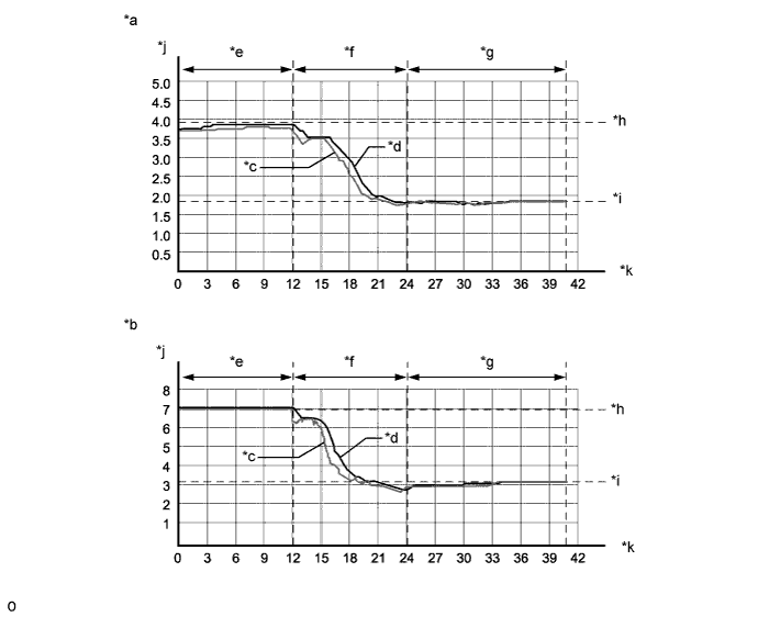
Text in Illustration *a Air-fuel ratios when exhaust-gas recirculation active *b Air-fuel ratios when exhaust-gas recirculation off *c Signal from air fuel ratio sensor upstream of oxidation catalytic converter *d Signal from air fuel ratio sensor downstream of oxidation catalytic converter *e No auxiliary functions activated *f Successive activation of auxiliary functions *g Auxiliary function activated *h Air-fuel ratios level during idling with no auxiliary functions activated *i Air-fuel ratios level during idling with auxiliary functions activated *j [Air-fuel ratio] *k [Second] - - -
-
Fully depress the accelerator pedal, and then measure the values after releasing the pedal.
Tech Tips
The air-fuel ratios behave as follows when the accelerator is pressed:
-
Operating the accelerator pedal assembly: The engine acceleration and corresponding increase in fuel quantity lowers the air-fuel ratios.
-
Keeping the accelerator pedal assembly pressed: Keeping the accelerator pedal assembly pressed (engine runs at maximum speed) stabilizes the air-fuel ratios a level considerably higher than the idling level.
-
Releasing the accelerator pedal assembly: The fuel injection is switched off until the engine returns to idling speed. During this phase, the air-fuel ratios increase to a maximum value of 32.7 until the idling speed is reached and fuel injection is resumed.
-
The following illustration shows how the air-fuel ratios can behave when the accelerator is pressed.
-
When exhaust-gas recirculation is turned off, the air-fuel ratios during the idling phase will be somewhat higher than those shown in this example.
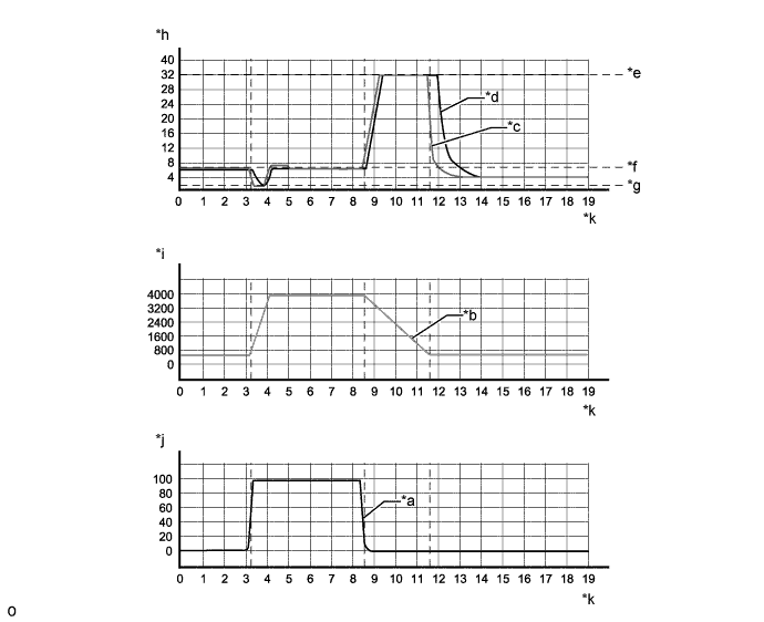
Text in Illustration *a Accelerator pedal assembly signal *b Engine speed *c Signal from air fuel ratio sensor upstream of oxidation catalytic converter *d Signal from air fuel ratio sensor downstream of oxidation catalytic converter *e Air-fuel ratios level during overrun fuel cut-off *f Air-fuel ratios level at maximum speed *g Air-fuel ratios level immediately after complete operation of accelerator pedal assembly *h [Air-fuel ratio] *i [rpm] *j [%] *k [Second] - - -
-
-
PROCEDURE
-
CHECK HARNESS AND CONNECTOR (AIR FUEL RATIO SENSOR (FOR SENSOR 2) - ECM)
-
Disconnect the air fuel ratio sensor (for sensor 2) connector.
-
Disconnect the ECM connector.
-
Measure the resistance according to the value(s) in the table below.
Standard Resistance Tester Connection Condition Specified Condition C121-1 (AF2+) - C112-130 (AF2+) Always Below 1 Ω C121-2 (AF2-) - C112-133 (AF2-) Always Below 1 Ω C121-3 (HAF2) - C112-17 (HAF2) Always Below 1 Ω C121-5 (TR2) - C112-131 (TR2) Always Below 1 Ω C121-6 (RE2) - C112-134 (RE2) Always Below 1 Ω C121-1 (AF2+) or C112-130 (AF2+) - Body ground Always 10 kΩ or higher C121-2 (AF2-) or C112-133 (AF2-) - Body ground Always 10 kΩ or higher C121-3 (HAF2) or C112-17 (HAF2) - Body ground Always 10 kΩ or higher C121-5 (TR2) or C112-131 (TR2) - Body ground Always 10 kΩ or higher C121-6 (RE2) or C112-134 (RE2) - Body ground Always 10 kΩ or higher
NG 
REPAIR OR REPLACE HARNESS OR CONNECTOR Click here
OK 
-
-
CHECK EXHAUST SYSTEM
-
Check for exhaust gas leaks from the installation area of the air fuel ratio sensor (for sensor 2).
OK No exhaust gas leak.
NG
REPAIR OR REPLACE EXHAUST SYSTEM Click here
OK
-
-
CHECK AIR FUEL RATIO SENSOR (FOR SENSOR 2)
-
Check the air fuel ratio sensor for tightness and damages.
OK No damage. -
Check for soot deposits in the air fuel ratio sensor (for sensor 2).
OK No soot deposits.
NG
REPAIR OR REPLACE AIR FUEL RATIO SENSOR (FOR SENSOR 2) Click here
OK
-
-
REPLACE AIR FUEL RATIO SENSOR (FOR SENSOR 2)
-
Replace the air fuel ratio sensor (for sensor 2) Click here.
-
Perform the O2 sensor learning value reset Click here.
NEXT
CONFIRM WHETHER MALFUNCTION HAS BEEN SUCCESSFULLY REPAIRED Click here
-
-
REPAIR OR REPLACE HARNESS OR CONNECTOR
-
Repair or replace the harness or connector.
NEXT
CONFIRM WHETHER MALFUNCTION HAS BEEN SUCCESSFULLY REPAIRED Click here
-
-
REPAIR OR REPLACE EXHAUST SYSTEM
-
Repair or replace the exhaust system.
-
Repair the area where leaks were found or replace parts.
-
NEXT
CONFIRM WHETHER MALFUNCTION HAS BEEN SUCCESSFULLY REPAIRED Click here
-
-
REPAIR OR REPLACE AIR FUEL RATIO SENSOR (FOR SENSOR 2)
-
Repair or replace the air fuel ratio sensor (for sensor 2).
-
Apply compressed air to remove soot stuck to the air fuel ratio sensor. If soot cannot be removed, replace the air fuel ratio sensor.
Tech Tips
When the air fuel ratio sensor is replaced, perform initialization.
-
NEXT
CONFIRM WHETHER MALFUNCTION HAS BEEN SUCCESSFULLY REPAIRED Click here
-
-
CONFIRM WHETHER MALFUNCTION HAS BEEN SUCCESSFULLY REPAIRED
-
Connect the GTS to the DLC3.
-
Turn the ignition switch to ON and turn the GTS on.
-
Clear the DTCs Click here.
-
Turn the ignition switch off and wait for 60 seconds or more [A].
-
Perform road test [B].
-
Repeat [A] and [B] for the number of trips detected.
-
Enter the following menus: Powertrain / Engine and ECT / Trouble Codes.
-
Confirm that the DTC is not output again.
NEXT 
END
-