СИСТЕМА ECD (для клапана регулирования всасывания) КОНТАКТЫ ECM
Tech Tips
-
The standard voltage between each pair of the ECM terminals is shown in the table below. The appropriate conditions for checking each pair of the terminals are also indicated.
-
The result of checks should be compared with the standard voltage for that pair of terminals, and displayed in the "Specified Condition" column.
-
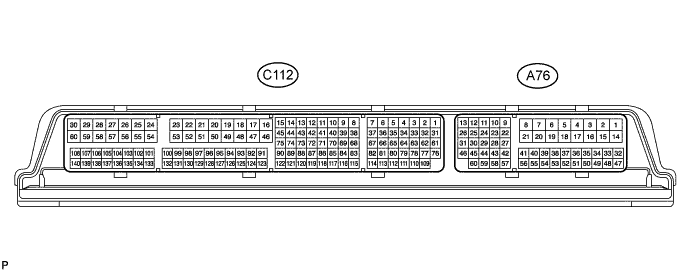
The illustration above can be used as a reference to identify the ECM terminal locations.
| Terminal No. (Symbol) | Wiring Color | Terminal Description | Condition | Specified Condition |
|---|---|---|---|---|
| A76-2 (+B) - A76-17 (E3) | B - W-B | Power source of ECM | Ignition switch ON | 11 to 14 V |
| A76-14 (+B2) - A76-17 (E3) | B - W-B | Power source of ECM | Ignition switch ON | 11 to 14 V |
| A76-1 (+B3) - A76-17 (E3) | B - W-B | Power source of ECM | Ignition switch ON | 11 to 14 V |
| A76-9 (MREL) - A76-17 (E3) | W - W-B | EFI MAIN relay | Ignition switch ON | 11 to 14 V |
| 45 seconds elapsed since ignition switch off | 0 to 1.5 V | |||
| A76-15 (BATT) - A76-17 (E3) | B - W-B | Battery (for measuring the battery voltage and for the ECM memory) | Always | 11 to 14 V |
| A76-37 (IGSW) - A76-17 (E3) | B - W-B | Ignition switch signal | Ignition switch ON | 11 to 14 V |
| A76-52 (VPA) - A76-22 (EPA) | W - R | Accelerator pedal sensor assembly (for engine control) | Ignition switch ON, accelerator pedal fully released | 0.5 to 1.1 V |
| Ignition switch ON, accelerator pedal fully depressed | 2.6 to 4.5 V | |||
| A76-43 (VPA2) - A76-23 (EPA2) | Y - G | Accelerator pedal sensor assembly (for sensor malfunction detection) | Ignition switch ON, accelerator pedal fully released | 1.2 to 2.0 V |
| Ignition switch ON, accelerator pedal fully depressed | 3.4 to 4.75 V | |||
| A76-27 (VCPA) - A76-22 (EPA) | L - R | Power source of accelerator pedal sensor assembly (for VPA) | Ignition switch ON | 4.5 to 5.5 V |
| A76-29 (VCP2) - A76-23 (EPA2) | LG - G | Power source of accelerator pedal sensor assembly (for VPA2) | Ignition switch ON | 4.5 to 5.5 V |
| C112-83 (VCTA) - C112-81 (ETA) | L-W - BR-O | Power source of diesel throttle position sensor | Ignition switch ON | 4.5 to 5.5 V |
| C112-117 (VTA1) - C112-81 (ETA) | GR-W - BR-O | Diesel throttle position sensor | Throttle valve fully opened | 3.2 to 4.9 V |
| Throttle valve fully closed | 0.5 to 1.1 V | |||
| C112-50 (M+) - C112-20 (M-) | W-R - W-L | Diesel throttle duty signal | Idling with warm engine | Pulse generation (See waveform 1) |
| C112-46 (HAF1) - A76-5 (E2) | W-Y - W-B | Air fuel ratio sensor heater (for sensor 1) | Ignition switch ON | 11 to 14 V |
| Idling | Pulse generation (See waveform 2) |
|||
| C112-127 (AF1+) - A76-5 (E2) | GR-BR - W-B | Air fuel ratio sensor signal (for sensor 1) | Idling with warm engine | 1.5 to 4.9 V |
| C112-126 (AF1-) - A76-5 (E2) | BR - W-B | Air fuel ratio sensor signal (for sensor 1) | Idling with warm engine | 2.35 to 2.65 V |
| C112-128 (TR1) - A76-5 (E2) | GR-L - W-B | Air fuel ratio sensor signal (for sensor 1) | Idling with warm engine | 1.5 to 4.9 V |
| C112-125 (RE1) - A76-5 (E2) | B-Y - W-B | Air fuel ratio sensor signal (for sensor 1) | Idling with warm engine | 2.1 to 3.5 V |
| C112-93 (THF) - C112-124 (ETHF) | L-G - BR-G | Fuel temperature sensor | Ignition switch ON | 0.5 to 2.0 V |
| C112-54 (VCS) - C112-102 (E2S) | L-W - BR-GR | Power source of fuel pressure sensor | Ignition switch ON | 4.5 to 5.5 V |
| C112-101 (PC) - C112-102 (E2S) | Y-GR - BR-GR | Fuel pressure sensor | Idling | 1.0 to 1.3 V |
| C112-97 (VG) - C112-129 (EVG) | Y-B - BR-B | Mass air flow meter signal | Ignition switch ON | Pulse generation (See waveform 3) |
| C112-114 (THA) - C112-129 (EVG) | GR-B - BR-B | Intake air temperature sensor (built into mass air flow meter) | Idling, intake air temperature 20°C (68°F) | 0.5 to 2.0 V |
| C112-30 (PCV) - A76-4 (E1) | W-V - W-B | Fuel quantity control valve | Idling | Pulse generation (See waveform 4) |
| C112-29 (IJ1+) - C112-59 (IJ1-) | R-W - BR-W | No. 1 injector assembly | Idling | Pulse generation (See waveform 5) |
| C112-28 (IJ2+) - C112-58 (IJ2-) | R-L - BR-L | No. 2 injector assembly | Idling | Pulse generation (See waveform 5) |
| C112-27 (IJ3+) - C112-57 (IJ3-) | R-Y - BR-Y | No. 3 injector assembly | Idling | Pulse generation (See waveform 5) |
| C112-26 (IJ4+) - C112-56 (IJ4-) | R-G - BR-G | No. 4 injector assembly | Idling | Pulse generation (See waveform 5) |
| C112-92 (THCI) - C112-91 (ETCI) | Y-L - BR-Y | Exhaust gas temperature sensor (for sensor 1) | Idling with warm engine | 2.9 to 3.3 V |
| C112-109 (THCO) - C112-110 (ETCO) | GR-W - BR | Exhaust gas temperature sensor (for sensor 2) | Idling with warm engine | 2.9 to 3.3 V |
| C112-82 (THW) - C112-113 (ETHW) | B-V - BR-B | Engine coolant temperature sensor | Idling, engine coolant temperature 60 to 120°C (140 to 248°F) | 0.2 to 1.0 V |
| C112-79 (THIA) - C112-89 (ETHI) | B-W - BR-W | Intake air temperature sensor | Idling, intake air temperature at 0 to 80°C (32 to 176°F) | 0.5 to 2.0 V |
| C112-61 (VPIM) - C112-76 (EPIM) | L-G - BR-L | Power source of turbo pressure sensor assembly | Ignition switch ON | 4.75 to 5.25 V |
| C112-111 (PIM) - C112-76 (EPIM) | B-L - BR-L | Turbo pressure sensor assembly | Ignition switch ON (same as atmosphere pressure) | 0.8 to 1.4 V |
| C112-65 (VNVC) - C112-112 (VNE2) | L-B - BR-O | Power source of nozzle vane position sensor | Ignition switch ON | 4.5 to 5.5 V |
| C112-80 (VTAI) - C112-112 (VNE2) | GR-W - BR-O | Nozzle vane position sensor | VN turbocharger fully closed | 0.9 to 2.1 V |
| VN turbocharger fully opened | 3.0 to 4.1 V | |||
| C112-51 (VN+A) - A76-4 (E1) | W - W-B | VN turbocharger motor | Idling with warm engine | Pulse generation (See waveform 6) |
| C112-21 (VN-A) - A76-4 (E1) | W-B - W-B | VN turbocharger motor | Idling with warm engine | Pulse generation (See waveform 7) |
| C112-16 (ECBV) - A76-4 (E1) | W-R - W-B | EGR cooler bypass switching valve assembly | Ignition switch ON with cold engine | 0 to 1.5 V |
| Idling with warm engine | 11 to 14 V | |||
| C112-69 (VCEG) - C112-84 (EEGL) | L - BR-G | Power source of EGR valve position sensor | Ignition switch ON | 4.5 to 5.5 V |
| C112-70 (VCPX) - C112-71 (EPEX) | L-GR - BR-O | Power source of differential pressure sensor | Ignition switch ON | 4.5 to 5.5 V |
| A76-7 (D) - A76-4 (E1) | W - W-B | No. 2 clutch start switch assembly | Ignition switch ON, clutch pedal released | 11 to 14 V |
| Ignition switch ON, clutch pedal depressed | 0 to 1.5 V | |||
| A76-36 (STA) - A76-4 (E1) | LG - W-B | Starter signal | Cranking | 6.0 V or higher |
| A76-21 (TACH) - A76-4 (E1) | GR - W-B | Engine speed | Idling | Pulse generation (See waveform 8) |
| A76-48 (STP) - A76-4 (E1) | V - W-B | Stop light switch assembly | Ignition switch ON, brake pedal depressed | 7.5 to 14 V |
| Ignition switch ON, brake pedal released | 0 to 1.5 V | |||
| A76-10 (ST1-) - A76-4 (E1) | R-W - W-B | Stop light switch assembly (opposite to STP) |
Ignition switch ON, brake pedal depressed | 0 to 1.5 V |
| Ignition switch ON, brake pedal released | 7.5 to 14 V | |||
| A76-51 (SPD) - A76-4 (E1) | Y - W-B | Speed signal from combination meter | Ignition switch ON, drive wheels rotating slowly | Pulse generation (See waveform 9) |
| A76-59 (W) - A76-4 (E1) | LG - W-B | MIL | MIL illuminated | Below 3 V |
| MIL not illuminated | 11 to 14 V | |||
| A76-50 (TC) - A76-4 (E1) | P - W-B | Terminal TC of DLC3 | Ignition switch ON | 11 to 14 V |
| A76-20 (FANL) - A76-4 (E1) | R - W-B | Cooling fan (low speed) | Ignition switch ON | 11 to 14 V |
| Idling with A/C on or high engine coolant temperature | Below 1.5 V | |||
| A76-45 (FANH) - A76-4 (E1) | W - W-B | Cooling fan (high speed) | Idling with high engine coolant temperature | Below 1.5 V |
| A76-30 (ELS2) - A76-4 (E1) | B - W-B | Electric load | Defogger switch ON | 7.5 to 14 V |
| Defogger switch off | 0 to 1.5 V | |||
| A76-32 (MHSW) - A76-4 (E1) | Y - W-B | Power heater switch signal | Power heater switch ON | 11 to 14 V |
| A76-11 (R) - A76-4 (E1) | R - W-B | Back-up light switch signal | Back-up light switch ON | 11 to 14 V |
| A76-26 (CANH) - A76-4 (E1) | Y - W-B | CAN communication line | Ignition switch ON | Pulse generation (See waveform 10) |
| A76-25 (CANL) - A76-4 (E1) | W - W-B | CAN communication line | Ignition switch ON | Pulse generation (See waveform 11) |
| A76-13 (CANP) - A76-4 (E1) | R - W-B | CAN communication line | Ignition switch ON | Pulse generation (See waveform 12) |
| A76-12 (CANN) - A76-4 (E1) | W - W-B | CAN communication line | Ignition switch ON | Pulse generation (See waveform 13) |
| C112-121 (NE+) - C112-90 (NE-) | B-R - BR-R | Crankshaft position sensor | Idling with warm engine | Pulse generation (See waveform 14) |
| C112-68 (G+) - C112-115 (G-) | Y-V - BR-Y | Camshaft position sensor | Idling with warm engine | Pulse generation (See waveform 15) |
| A76-60 (FC) - A76-4 (E1) | B - W-B | FUEL PUMP relay | Ignition switch ON | 11 to 14 V |
| Idling | Below 1.5 V | |||
| C112-74 (LIN) - C112-96 (EGCU) | V-W - BR-W | LIN communication | Ignition switch ON | Pulse generation (See waveform 16) |
| C112-85 (PEX) - C112-71 (EPEX) | B - BR-O | Differential pressure sensor | Ignition switch ON | 0.7 to 1.3 V |
| Idling with warm engine | 0.5 to 4.5 V | |||
| C112-24 (VCPE) - A76-4 (E1) | L - W-B | Power source of exhaust gas pressure sensor | Ignition switch ON | 4.5 to 5.5 V |
| C112-103 (PEXM) - C112-135 (EPEM) | Y - BR-O | Exhaust gas pressure sensor | Ignition switch ON (same as atmosphere pressure) | 0.7 to 1.3 V |
| C112-60 (PRV) - A76-5 (E2) | W-B - W-B | Pressure discharge valve | Ignition switch ON | Pulse generation (See waveform 17) |
| C112-130 (AF2+) - A76-5 (E2) | GR - W-B | Air fuel ratio sensor signal (for sensor 2) | Idling with warm engine | 1.5 to 4.9 V |
| C112-133 (AF2-) - A76-5 (E2) | BR-R - W-B | Air fuel ratio sensor signal (for sensor 2) | Idling with warm engine | 2.35 to 2.65 V |
| C112-131 (TR2) - A76-5 (E2) | GR-W - W-B | Air fuel ratio sensor signal (for sensor 2) | Idling with warm engine | 1.5 to 4.9 V |
| C112-134 (RE2) - A76-5 (E2) | B-W - W-B | Air fuel ratio sensor signal (for sensor 2) | Idling with warm engine | 2.1 to 3.5 V |
| C112-17 (HAF2) - A76-4 (E1) | W-G - W-B | Air fuel ratio sensor heater (for sensor 2) | Ignition switch ON | 11 to 14 V |
| Idling | Pulse generation (See waveform 2) |
|||
| C112-48 (EGM+) - C112-18 (EGM-) | GR-R - W-Y | EGR valve assembly (Motor) | Idling with warm engine | Pulse generation (See waveform 18) |
| C112-116 (EGLS) - C112-84 (EEGL) | B - BR-G | EGR valve assembly (Position sensor) | Idling with warm engine | 0.5 to 4.5 V |
| C112-72 (VAC1) - A76-5 (E2) | L-Y -W-B | Power source of swirl control valve | Ignition switch ON | 4.5 to 5.5 V |
| C112-87 (IAC1) - C112-119 (EAC1) | Y -BR-B | Swirl control valve (Position sensor) | Idling with warm engine | 0.5 to 4.5 V |
| C112-49 (IA1+) - C112-19 (IA1-) | W-GR - W-G | Swirl control valve (Motor) | Idling with warm engine | Pulse generation (See waveform 19) |
| C112-118 (THEC) - C112-86 (ETEC) | Y-L - BR-Y | EGR gas temperature sensor | Idling with warm engine | 0 to 5 V |
| A76-4 (E1) - Body ground | W-B - - | Ground | Always | Below 1 Ω |
| A76-5 (E2) - Body ground | W-B - - | Ground | Always | Below 1 Ω |
| A76-17 (E3) - Body ground | W-B - - | Ground | Always | Below 1 Ω |
| A76-18 (E4) - Body ground | W-B - - | Ground | Always | Below 1 Ω |
-
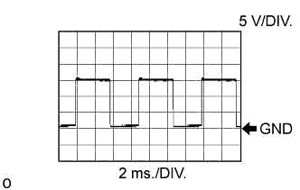
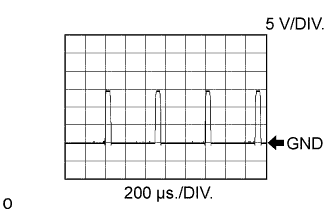
WAVEFORM 1
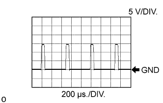
Diesel throttle duty signal Item Content ECM Terminal Name Between M+ and M- Tester Range 5 V/DIV., 200 μs./DIV. Condition Idling with warm engine -
WAVEFORM 2
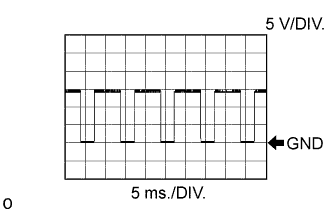
Air fuel ratio sensor heater signal Item Content ECM Terminal Name Between HAF1 and E2
Between HAF2 and E2
Tester Range 5 V/DIV., 5 ms./DIV. Condition Idling with warm engine -
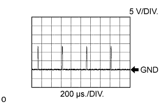
WAVEFORM 3
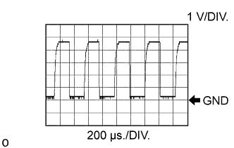
Mass air flow meter signal Item Content ECM Terminal Name Between VG and EVG Tester Range 1 V/DIV., 200 μs./DIV. Condition Ignition switch ON -
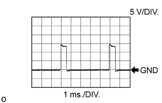
WAVEFORM 4
Fuel quantity control valve signal Item Content ECM Terminal Name Between PCV and E1 Tester Range 5 V/DIV., 2 ms./DIV. Condition Idling with warm engine -
WAVEFORM 5
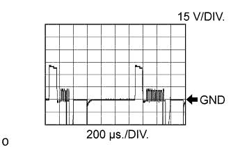
Injector signal Item Content ECM Terminal Name Between IJ1+ and IJ1-
Between IJ2+ and IJ2-
Between IJ3+ and IJ3-
Between IJ4+ and IJ4-
Tester Range 15 V/DIV., 200 μs./DIV. Condition Idling with warm engine -
WAVEFORM 6

VN turbocharger motor signal Item Content ECM Terminal Name Between VN+A and E1 Tester Range 5 V/DIV., 200 μs./DIV. Condition Idling with warm engine -
WAVEFORM 7
VN turbocharger motor signal Item Content ECM Terminal Name Between VN-A and E1 Tester Range 5 V/DIV., 200 μs./DIV. Condition Idling with warm engine -
WAVEFORM 8
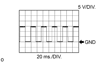
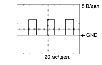
Engine speed signal Item Content ECM Terminal Name Between TACH and E1 Tester Range 5 V/DIV., 20 ms./DIV. Condition Idling with warm engine -
WAVEFORM 9
Vehicle speed signal Item Content ECM Terminal Name Between SPD and E1 Tester Range 5 V/DIV., 20 ms./DIV. Condition Ignition switch ON, drive wheels rotating slowly Tech Tips
The wavelength becomes shorter as the vehicle speed increases.
-
WAVEFORM 10
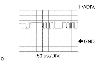
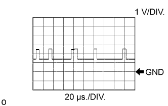
CAN communication signal Item Content ECM Terminal Name Between CANH and E1 Tester Range 1 V/DIV., 50 μs./DIV. Condition Ignition switch ON -
WAVEFORM 11
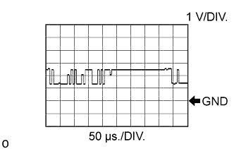
CAN communication signal Item Content ECM Terminal Name Between CANL and E1 Tester Range 1 V/DIV., 50 μs./DIV. Condition Ignition switch ON -
WAVEFORM 12
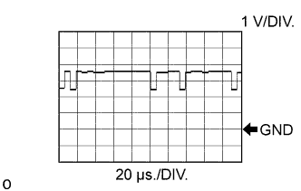
CAN communication signal Item Content ECM Terminal Name Between CANP and E1 Tester Range 1 V/DIV., 20 μs./DIV. Condition Ignition switch ON -
WAVEFORM 13
CAN communication signal Item Content ECM Terminal Name Between CANN and E1 Tester Range 1 V/DIV., 20 μs./DIV. Condition Ignition switch ON -
WAVEFORM 14
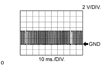
Crankshaft position sensor signal Item Content ECM Terminal Name Between NE+ and NE- Tester Range 2 V/DIV., 10 ms./DIV. Condition Idling with warm engine -
WAVEFORM 15
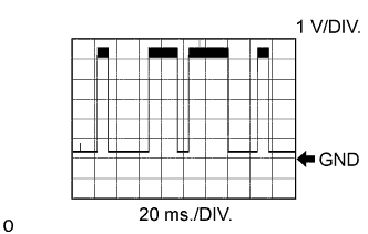
Camshaft position sensor signal Item Content ECM Terminal Name Between G+ and G- Tester Range 1 V/DIV., 20 ms./DIV. Condition Idling with warm engine -
WAVEFORM 16
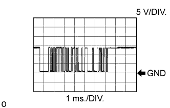
LIN communication signal Item Content ECM Terminal Name Between LIN and EGCU Tester Range 5 V/DIV., 1 ms./DIV. Condition Ignition switch ON -
WAVEFORM 17
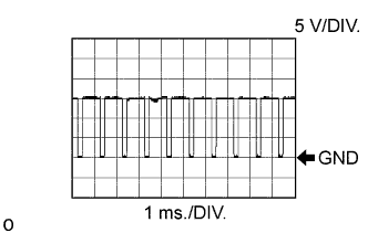
Pressure discharge valve signal Item Content ECM Terminal Name Between PRV and E2 Tester Range 5 V/DIV., 1 ms./DIV. Condition Ignition switch ON -
WAVEFORM 18
EGR valve motor signal Item Content ECM Terminal Name Between EGM+ and EGM- Tester Range 5 V/DIV., 200 μs./DIV. Condition Idling with warm engine -
WAVEFORM 19
Swirl control valve motor signal Item Content ECM Terminal Name Between IA1+ and IA1- Tester Range 5 V/DIV., 1 ms./DIV. Condition Idling with warm engine