СИСТЕМА ECD, Diagnostic DTC:P1212, P1213
| DTC Code | DTC Name |
|---|---|
| P1212 | Short Circuit to Battery Error |
| P1213 | Short Circuit to Ground Error |
DESCRIPTION
The EGR system recirculates exhaust gases in a way that suits every driving condition. The recirculated gas mixes with intake air. Therefore, the EGR system can slow combustion speed and keep the combustion temperature down. This helps reduce NOx emission.
In order to increase EGR circulation efficiency, the ECM adjusts the lift amount of the EGR valve and the throttle valve angle.
| DTC No. | DTC Detection Condition | Trouble Area |
|---|---|---|
| P1212 | Short to power source in vacuum switching valve assembly circuit for 0.22 seconds or more (3 trip detection logic) |
|
| DTC No. | DTC Detection Condition | Trouble Area |
|---|---|---|
| P1213 | Short to ground in vacuum switching valve assembly circuit for 0.22 seconds or more (3 trip detection logic) |
|
| DTC No. | Data List |
|---|---|
| P1212 P1213 |
|
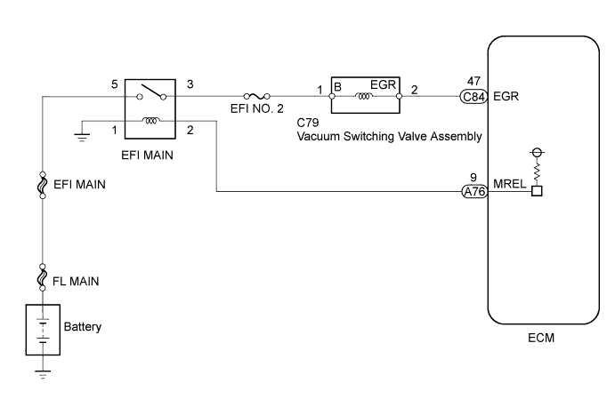
WIRING DIAGRAM
INSPECTION PROCEDURE
Note
-
When replacing the ECM, the ECM needs Registration and Initialization Click here.
-
Inspect the fuses for circuits related to this system before performing the following inspection procedure.
Tech Tips
-
When the ECM must be replaced, before replacing the ECM, perform the "Learning Values Save" function using the GTS. Then after installing the new ECM, perform all of the initialization/registrations for the "Learning Values Write" function by following the instructions shown on the GTS display.
-
Read freeze frame data using the GTS. Freeze frame data records the engine condition when malfunctions are detected. When troubleshooting, freeze frame data can help determine if the vehicle was moving or stationary, if the engine was warmed up or not, and other data from the time the malfunction occurred.
PROCEDURE
-
CHECK HARNESS AND CONNECTOR (VACUUM SWITCHING VALVE ASSEMBLY - ECM)
-
Disconnect the vacuum switching valve assembly connector.
-
Disconnect the ECM connector.
-
Measure the resistance according to the value(s) in the table below.
Standard Resistance Tester Connection Condition Specified Condition C79-2 (EGR) - C84-47 (EGR) Always Below 1 Ω C79-2 (EGR) or C84-47 (EGR) - Body ground Always 10 kΩ or higher
NG 
REPAIR OR REPLACE HARNESS OR CONNECTOR Click here
OK 
-
-
CHECK TERMINAL VOLTAGE (POWER SOURCE)
-
Disconnect the vacuum switching valve assembly connector.
-
Measure the voltage according to the value(s) in the table below.
Standard Voltage Tester Connection Switch Condition Specified Condition C79-1 (B) - Body ground Ignition switch ON 11 to 14 V
NG
REPAIR OR REPLACE HARNESS OR CONNECTOR Click here
OK
-
-
REPLACE VACUUM SWITCHING VALVE ASSEMBLY
-
Replace the vacuum switching valve assembly Click here.
NEXT
-
-
CHECK WHETHER DTC OUTPUT RECURS (DTC P1212 OR P1213)
-
Connect the GTS to the DLC3.
-
Turn the ignition switch to ON and turn the GTS on.
-
Clear the DTCs Click here.
-
Turn the ignition switch off and wait for 60 seconds or more [A].
-
Turn the ignition switch to ON and wait for 15 seconds or more [B].
-
Repeat [A] and [B] for the number of trips detected.
-
Enter the following menus: Engine and ECT / Trouble Codes.
-
Read the DTCs.
Result Result Proceed to No DTC output A DTC P1212 or P1213 B
B
REPLACE ECM Click here
A 
END
-
-
REPAIR OR REPLACE HARNESS OR CONNECTOR
-
Repair or replace the harness or connector.
NEXT
CONFIRM WHETHER MALFUNCTION HAS BEEN SUCCESSFULLY REPAIRED Click here
-
-
REPLACE ECM
-
Replace the ECM Click here.
NEXT
-
-
CONFIRM WHETHER MALFUNCTION HAS BEEN SUCCESSFULLY REPAIRED
-
Connect the GTS to the DLC3.
-
Turn the ignition switch to ON and turn the GTS on.
-
Clear the DTCs Click here.
-
Turn the ignition switch off and wait for 60 seconds or more [A].
-
Turn the ignition switch to ON and wait for 15 seconds or more [B].
-
Repeat [A] and [B] for the number of trips detected.
-
Enter the following menus: Engine and ECT / Trouble Codes.
-
Confirm that the DTC is not output again.
NEXT
END
-