СИСТЕМА ECD ДАННЫЕ ФИКСИРОВАННОГО НАБОРА ПАРАМЕТРОВ
-
DESCRIPTION
The ECM records vehicle and driving condition information as freeze frame data the moment a DTC is stored. When troubleshooting, freeze frame data can help determine if the vehicle was moving or stationary, if the engine was warmed up or not, and other data from the time the malfunction occurred.
Tech Tips
If it is impossible to duplicate the problem even though a DTC is detected, confirm the freeze frame data.
-
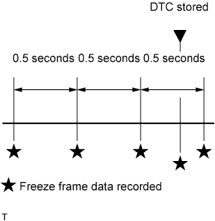
The ECM records engine conditions in the form of freeze frame data every 0.5 seconds. Using the GTS, 5 separate sets of freeze frame data can be checked.
-
3 data sets before the DTC was stored.
-
1 data set when the DTC was stored.
-
1 data set after the DTC was stored.
-
These data sets can be used to simulate the condition of the vehicle around the time of the occurrence of the malfunction. The data may assist in identifying the cause of the malfunction, and in judging whether it was temporary or not.
-
-
LIST OF FREEZE FRAME DATA
GTS Display Vehicle Speed Engine Speed Calculate Load MAF Atmosphere Pressure MAP Coolant Temp Intake Air Intake Air Temp (Turbo) Supported Intake Air Temp (Turbo) Engine Run Time Battery Voltage Accel Sens. No.1 Volt % Accel Sens. No.2 Volt % Target Throttle Position Supported Target Throttle Position Target Throttle Position #2 Supported Target Throttle Position #2 Actual Throttle Position Supported Actual Throttle Position Actual Throttle Position #2 Supported Actual Throttle Position #2 Throttle Sensor Volt % Main Injection Timing Target Common Rail Pressure Supported Target Common Rail Pressure Common Rail Pressure Supported Common Rail Pressure Fuel Temperature Supported Fuel Temperature A/F Lambda B1S1 AFS Current B1S1 Target EGR Position Target EGR Valve Pos Supported Target EGR Valve Pos Target EGR Valve Pos #2 Supported Target EGR Valve Pos #2 Actual EGR Valve Pos Supported Actual EGR Valve Pos Actual EGR Valve Pos #2 Supported Actual EGR Valve Pos #2 Target Booster Pressure Supported Target Booster Pressure VN Turbo Command Supported Target VN Turbo Position VN Turbo Command #2 Supported Target VN Turbo Position #2 Actual VN Position Supported Actual VN Turbo Position Actual VN Position #2 Supported Actual VN Turbo Position #2 Exhaust Temperature B1S1 Supported Exhaust Temperature B1S1 Exhaust Temperature B1S2 Supported Exhaust Temperature B1S2 Exhaust Temperature B1S3 Supported Exhaust Temperature B1S3 DPF Differential Pressure Supported DPF Differential Pressure Starter Signal Clutch Switch Stop Light Switch Shift Indication Enable TC Terminal # Codes (Include History) Time after DTC Cleared Distance from DTC Cleared Warmup Cycle Cleared DTC Electrical Load Signal 1 Electrical Load Signal 2 Shift SW Status (R Range) MT Down Shift Indication MT Up Shift Indication Total Air Mass Flow Into the Engine Air Mass Per Cylinder Intake Valve Upstream Pressure Actual Air Temperature at Air Flow Meter Temperature Down Stream of Charged Air Cooler Desired Air Mass Gas Mass Flow Downstream of the Intake Manifold Gas Mass Flow Upstream of the Intake Manifold EGR Valve (Duty Cycle) EGR Valve (Output-Duty Cycle) First Learnt Offset-Value of EGR Valve Last Learnt Offset-Value of EGR Valve Offset-Value of EGR Valve in Actual Driving Cycle EGR Cooler Bypass Valve Pedal Signal Filtered Raw Value of Pedal Signal 1 (from Encoder) Raw Value of Pedal Signal 2 (from Encoder) Duty Cycle of Throttle Valve (Output) Throttle Valve Actuator Position Average Engine Speed of One Cylinder Segment State of EPM Synchronisation Engine Rotation Specific Cylinder 1 (Ignition Order) Engine Rotation Specific Cylinder 2 (Ignition Order) Engine Rotation Specific Cylinder 3 (Ignition Order) Engine Rotation Specific Cylinder 4 (Ignition Order) Cylinder 1 Quantity Compensation Cylinder 2 Quantity Compensation Cylinder 3 Quantity Compensation Cylinder 4 Quantity Compensation Quantity Regulation Valve - Current Value from Common Rail Quantity Regulation Valve - Output Duty Cycle Filtered Pressure Value at Particle Filter Upstream (EU5) Exhaust Temp Sensor THCI (Corrected Value) The Upstream Temperature in Particle Filter (Exhaust Temp) Remaining Distance for DPF Distance Since Last Succeeded Regeneration Regeneration Demand Status Regeneration Interruption Regeneration Locked/Inhibited Engine Operation Since Last Succeeded Regeneration Rail Pressure Value State of the Rail Pressure Governor Control Maximum Rail Pressure of the Last 10ms Duty Cycle for Turbo Charger Actuator (Output) Turbo Charger Actuator Position Air Pressure Value Coolant Temperature at Engine Output Engine Temperature Environment Pressure Temperature of Environment Air Injection Quantity Actual Value Power Consumption of GCU (Actual Value) Active Operation Mode Actual Vehicle Range (km) Raw Load on the Alternator Air Condition Status Diesel Filter Heating Current Status OPSW(Oil Pressure) FFB1 FFB2 Brake Cancel Switch