СИСТЕМА ECD (для клапана регулирования всасывания), Diagnostic DTC:P200E
| DTC Code | DTC Name |
|---|---|
| P200E | Catalyst System Over Temperature Bank 1 |
DESCRIPTION
| DTC No. | DTC Detection Condition | Trouble Area |
|---|---|---|
| P200E | When exhaust gas temperature sensor (for sensor 1) value exceeds upper limit for 0.3 seconds. (3 trip detection logic) |
|
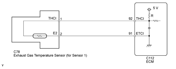
WIRING DIAGRAM
INSPECTION PROCEDURE
Note
When replacing the ECM, the ECM needs Registration and Initialization Click here.
Tech Tips
-
When the ECM must be replaced, before replacing the ECM, perform the "Learning Values Save" function using the GTS. Then after installing the new ECM, perform all of the initialization/registrations for the "Learning Values Write" function by following the instructions shown on the GTS display.
-
Read freeze frame data using the GTS. Freeze frame data records the engine condition when malfunctions are detected. When troubleshooting, freeze frame data can help determine if the vehicle was moving or stationary, if the engine was warmed up or not, and other data from the time the malfunction occurred.
PROCEDURE
-
PERFORM ACTIVE TEST USING GTS (ACTUATOR TEST OF THROTTLE VALVE)
-
Connect the GTS to the DLC3.
-
Turn the ignition switch to ON and turn the GTS on.
-
Enter the following menus: Powertrain / Engine and ECT / Active Test / Actuator Test of Throttle Valve / Data List / Throttle Valve Actuator Position.
-
Perform the following steps 1 to 4.
-
Step 1
-
Perform Active Test of throttle valve with control value of 5% (opening ratio in %).
-
Monitor the difference of the control value and Throttle Valve Actuator Position value (0 +/-3%). Throttle valve must operate within 1 second.
-
-
Step 2
-
Wait for 2 seconds or more.
-
-
Step 3
-
Perform Active Test of throttle valve with control value of 91% (opening ratio in %).
-
Monitor the difference of the control value and Throttle Valve Actuator Position value (0 +/-3%). Throttle valve must operate within 1 second.
-
-
Step 4
-
Wait for 2 seconds or more.
-
-
Perform the above steps 1 to 4 and check that the part operates as specified.
OK Part operates as specified.
NG 
REPLACE DIESEL THROTTLE BODY Click here
OK 
-
-
PERFORM ACTIVE TEST USING GTS (ACTUATOR TEST OF SWIRL FLAP)
-
Connect the GTS to the DLC3.
-
Turn the ignition switch to ON and turn the GTS on.
-
Start the engine.
-
Enter the following menus: Powertrain / Engine and ECT / Active Test / Actuator Test of Swirl Flap / Data List / Swirl Valve Actuator Position.
OK The value of "Swirl Valve Actuator Position" changes according to the amount "Actuator Test of Swirl Flap" is operated, and the swirl flap operates smoothly.
NG
REPLACE SWIRL CONTROL VALVE Click here
OK
-
-
PERFORM ACTIVE TEST USING GTS (ACTUATOR TEST OF TURBO CHARGER)
-
Connect the GTS to the DLC3.
-
Turn the ignition switch to ON and turn the GTS on.
-
Start the engine.
-
Enter the following menus: Powertrain / Engine and ECT / Active Test / Actuator Test of Turbo Charger.
-
Set the control value to 5%. The variable nozzle vane turbocharger must operate within 1 second. Valve travel when adjusted is approximately 15 mm.
-
Wait for 2 seconds and set the control value to 95%. The variable nozzle vane turbocharger must operate within 1 second. Valve travel when adjusted is approximately 15 mm.
-
Wait for 2 seconds and stop the operation using the variable nozzle vane turbocharger Active Test.
OK Operates smoothly when above procedure is performed. Tech Tips
Check the movement of the variable turbine (stiffness, interference with other parts, etc.).
NG
REPLACE TURBOCHARGER SUB-ASSEMBLY Click here
OK
-
-
READ VALUE USING GTS (EXHAUST TEMPERATURE B1S1)
-
Connect the GTS to the DLC3.
-
Start the engine and warm it up.
-
Turn the GTS on.
-
Enter the following menus: Powertrain / Engine and ECT / Data List / Exhaust Temperature B1S1.
-
Read the value.
Standard Same as the actual exhaust gas temperature (50 to 700°C [122 to 1292°F] during idling after warm-up). Result Result Proceed to 800°C (1472°F) A Same as the actual exhaust gas temperature (50 to 700°C [122 to 1292°F] during idling after warm-up) B Tech Tips
-
If there is an open circuit, the GTS indicates -40°C (-40°F).
-
If there is a short circuit, the GTS indicates 800°C (1472°F).
-
B
CONFIRM WHETHER MALFUNCTION HAS BEEN SUCCESSFULLY REPAIRED Click here
A
-
-
READ VALUE USING GTS (CHECK FOR SHORT IN WIRE HARNESS)
-
Disconnect the exhaust gas temperature sensor (for sensor 1) connector.
-
Connect the GTS to the DLC3.
-
Turn the ignition switch to ON and turn the GTS on.
-
Enter the following menus: Powertrain / Engine and ECT / Data List / Exhaust Temperature B1S1.
-
Read the value.
Standard value -40°C (-40°F)
OK
REPLACE EXHAUST GAS TEMPERATURE SENSOR (FOR SENSOR 1) Click here
NG
CHECK HARNESS AND CONNECTOR (EXHAUST GAS TEMPERATURE SENSOR (FOR SENSOR 1) - ECM) Click here
-
-
CHECK HARNESS AND CONNECTOR (EXHAUST GAS TEMPERATURE SENSOR (FOR SENSOR 1) - ECM)
-
Disconnect the exhaust gas temperature sensor (for sensor 1) connector.
-
Disconnect the ECM connector.
-
Measure the resistance according to the value(s) in the table below.
Standard Resistance Tester Connection Condition Specified Condition C78-1 (THCI) or C112-92 (THCI) - Body ground Always 10 kΩ or higher
OK
REPLACE ECM Click here
NG
REPAIR OR REPLACE HARNESS OR CONNECTOR Click here
-
-
REPLACE DIESEL THROTTLE BODY
-
Replace the diesel throttle body Click here.
NEXT
CONFIRM WHETHER MALFUNCTION HAS BEEN SUCCESSFULLY REPAIRED Click here
-
-
REPLACE SWIRL CONTROL VALVE
-
Replace the swirl control valve Click here.
-
Perform the swirl valve learning value reset Click here.
NEXT
CONFIRM WHETHER MALFUNCTION HAS BEEN SUCCESSFULLY REPAIRED Click here
-
-
REPLACE TURBOCHARGER SUB-ASSEMBLY
-
Replace the turbocharger sub-assembly Click here.
NEXT
CONFIRM WHETHER MALFUNCTION HAS BEEN SUCCESSFULLY REPAIRED Click here
-
-
REPLACE ECM
-
Replace the ECM Click here.
NEXT
CONFIRM WHETHER MALFUNCTION HAS BEEN SUCCESSFULLY REPAIRED Click here
-
-
REPLACE EXHAUST GAS TEMPERATURE SENSOR (FOR SENSOR 1)
-
Replace the exhaust gas temperature sensor (for sensor 1) Click here.
NEXT
CONFIRM WHETHER MALFUNCTION HAS BEEN SUCCESSFULLY REPAIRED Click here
-
-
REPAIR OR REPLACE HARNESS OR CONNECTOR
-
Repair or replace the harness or connector.
NEXT
-
-
CONFIRM WHETHER MALFUNCTION HAS BEEN SUCCESSFULLY REPAIRED
-
Connect the GTS to the DLC3.
-
Turn the ignition switch to ON and turn the GTS on.
-
Clear the DTCs Click here.
-
Turn the ignition switch off and wait for 60 seconds or more [A].
-
Perform road test [B].
-
Repeat [A] and [B] for the number of trips detected.
-
Enter the following menus: Powertrain / Engine and ECT / Trouble Codes.
-
Confirm that the DTC is not output again.
NEXT 
END
-