INVERTER WITH CONVERTER REMOVAL
PROCEDURE
-
PRECAUTION
-
REMOVE SERVICE PLUG GRIP
-
DRAIN COOLANT (for Inverter)
-
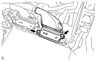
REMOVE CONNECTOR COVER ASSEMBLY
CAUTION:
-
Do not touch the high voltage connectors and terminals for 10 minutes after the service plug grip is removed.
-
Wear insulated gloves.
Note
Do not start the hybrid system with the service plug grip removed because it may cause a malfunction.
-
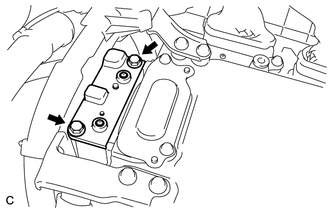
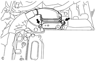
Remove the 2 bolts and connector cover assembly from the inverter with converter assembly.
Note
-
Make sure to pull the connector cover assembly straight up, as a connector is connected to the bottom of the cover.
-
Do not allow any foreign matter or water to enter the inverter with converter assembly.
-
-
-
CHECK TERMINAL VOLTAGE
CAUTION:
Wear insulated gloves.
Note
Do not allow any foreign matter or water to enter the inverter with converter assembly.
-
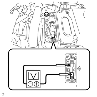
Using a voltmeter, measure the voltage between the terminals.
Standard voltage 0 V Tech Tips
Use a measuring range of DC 750 V or more on the voltmeter.
-
-
TEMPORARILY INSTALL CONNECTOR COVER ASSEMBLY
CAUTION:
Wear insulated gloves.
-
Temporarily install the connector cover assembly with the bolt to prevent any foreign matter or water from entering the inverter with converter assembly.
-
-
REMOVE COOL AIR INTAKE DUCT SEAL
-
REMOVE INLET AIR CLEANER ASSEMBLY
-
REMOVE AIR CLEANER CAP SUB-ASSEMBLY
-
REMOVE AIR CLEANER FILTER ELEMENT
-
REMOVE AIR CLEANER CASE SUB-ASSEMBLY
-
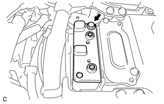
REMOVE NO. 5 INVERTER BRACKET
-
Remove the 2 bolts and No. 5 inverter bracket.
-
-
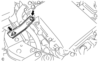
REMOVE NO. 4 INVERTER BRACKET
-
Remove the 3 bolts and No. 4 inverter bracket.
-
-
REMOVE UPPER INVERTER COVER
CAUTION:
Wear insulated gloves.
-
Remove the 2 bolts and upper inverter cover (generator cable side) from the inverter with converter assembly.
Note
-
Make sure to pull the upper inverter cover straight up, as a connector is connected to the bottom of the cover.
-
Do not touch the upper inverter cover waterproofing rubber.
-
-
-
DISCONNECT GENERATOR CABLE
CAUTION:
Wear insulated gloves.
-
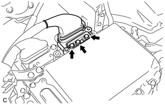
Using an insulated tool, remove the 3 bolts from the inverter with converter assembly.
-
Disconnect the 2 wire harness clamps and generator cable.
Note
-
Do not damage the terminals, connector housings or inverter with converter assembly during disconnection.
-
Do not touch the connector waterproofing rubber or terminals.
-
Insulate the removed terminals with insulating tape.
-
Do not allow any foreign matter or water to enter the inverter with converter assembly.
-
-
-
REMOVE UPPER INVERTER COVER
CAUTION:
Wear insulated gloves.
-
Remove the 2 bolts and upper inverter cover (motor cable side) from the inverter with converter assembly.
Note
-
Make sure to pull the upper inverter cover straight up, as a connector is connected to the bottom of the cover.
-
Do not touch the upper inverter cover waterproofing rubber.
-
-
-
DISCONNECT MOTOR CABLE
CAUTION:
Wear insulated gloves.
-
Using an insulated tool, remove the 3 bolts from the inverter with converter assembly.
-
Disconnect the 3 wire harness clamps and motor cable.
Note
-
Do not damage the terminals, connector housings or inverter with converter assembly during disconnection.
-
Do not touch the connector waterproofing rubber or terminals.
-
Insulate the removed terminals with insulating tape.
-
Do not allow any foreign matter or water to enter the inverter with converter assembly.
-
-
-
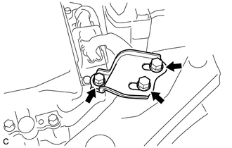
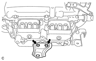
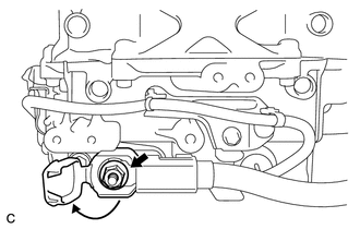
REMOVE NO. 3 MOTOR CABLE BRACKET
-
Disconnect the hose clamp from the No. 3 motor cable bracket.
Note
Do not remove the hose clamp from the hose.
-
Remove the 2 bolts and No. 3 motor cable bracket from the inverter with converter assembly.
-
-
REMOVE CONNECTOR COVER ASSEMBLY
CAUTION:
Wear insulated gloves.
-
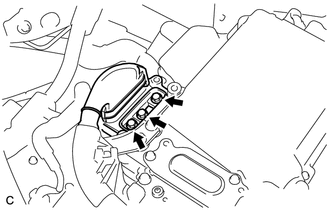
Remove the bolt and connector cover assembly from the inverter with converter assembly.
Note
-
Make sure to pull the connector cover assembly straight up, as a connector is connected to the bottom of the cover.
-
Do not allow any foreign matter or water to enter the inverter with converter assembly.
-
-
-
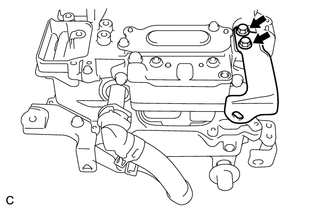
DISCONNECT NO. 4 ENGINE WIRE
CAUTION:
Wear insulated gloves.
-
Disconnect the No. 4 engine wire from the inverter with converter assembly.
Note
-
Do not damage the terminals, connector housings or inverter with converter assembly during disconnection.
-
Do not touch the connector waterproofing rubber or terminals.
-
Insulate the removed terminals with insulating tape.
-
Do not allow any foreign matter or water to enter the inverter with converter assembly.
-
-
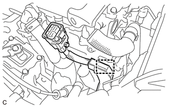
Disconnect the wire harness clamp from the No. 2 motor cable bracket.
-
-
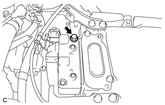
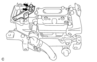
DISCONNECT FRAME WIRE
CAUTION:
Wear insulated gloves.
-
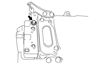
Remove the bolt from the inverter with converter assembly.
-
Disconnect the wire harness clamp and frame wire.
Note
-
Do not damage the terminals, connector housings or inverter with converter assembly during disconnection.
-
Do not touch the connector waterproofing rubber or terminals.
-
Insulate the removed terminals with insulating tape.
-
Do not allow any foreign matter or water to enter the inverter with converter assembly.
-
-
-
TEMPORARILY INSTALL CONNECTOR COVER ASSEMBLY
CAUTION:
Wear insulated gloves.
-
Temporarily install the connector cover assembly with the bolt to prevent any foreign matter or water from entering the inverter with converter assembly.
-
-
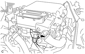
DISCONNECT LOW VOLTAGE CONNECTOR
CAUTION:
Wear insulated gloves.
-
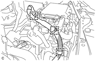
Raise the lock lever and disconnect the 3 low voltage connectors from the inverter with converter assembly.
Note
-
Insulate the removed terminals with insulating tape.
-
Do not allow any foreign matter or water to enter the inverter with converter assembly.
-
-
-
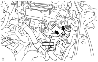
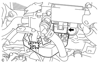
DISCONNECT NO. 3 ENGINE ROOM WIRE
-
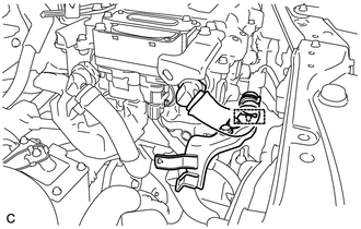
Remove the relay block cover from the engine room relay block and junction block assembly.
-
Remove the nut from the engine room relay block and junction block assembly.
-
Disconnect the wire harness clamp and No. 3 engine room wire from the engine room relay block and junction block assembly.
-
-
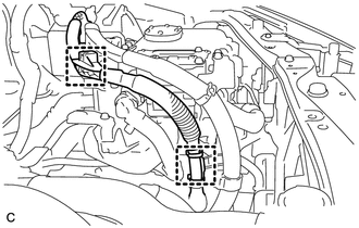
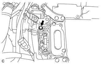
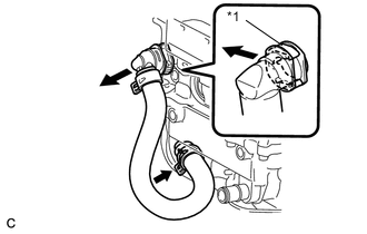
REMOVE NO. 4 INVERTER COOLING HOSE
-
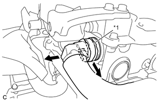
Text in Illustration *1 Retainer Release the retainer and disconnect the No. 4 inverter cooling hose from the inverter with converter assembly.
-
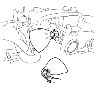
Put pieces of cloth into the pipes and in the disconnected hoses, or cover the pipes and hoses with plastic bags as shown in the illustration to prevent foreign matter from entering the cooling system and to prevent coolant from spilling near the inverter with converter assembly.
-
-
REMOVE NO. 1 INVERTER COOLING HOSE ASSEMBLY
-
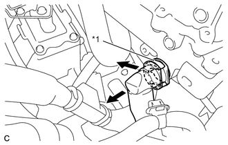
Text in Illustration *1 Retainer Release the retainer and disconnect the No. 1 inverter cooling hose assembly from the inverter with converter assembly.
-
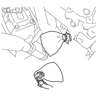
Put pieces of cloth into the pipes and in the disconnected hoses, or cover the pipes and hoses with plastic bags as shown in the illustration to prevent foreign matter from entering the cooling system and to prevent coolant from spilling near the inverter with converter assembly.
-
-
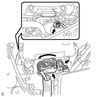
REMOVE INVERTER WITH CONVERTER ASSEMBLY
CAUTION:
Wear insulated gloves.
-
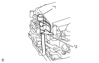
Text in Illustration *1 No. 3 Engine Room Wire *2 Hook Temporarily secure the No. 3 engine room wire with the inverter with converter assembly hook as shown in the illustration.
-
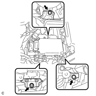
Remove the 2 bolts, nut and inverter with converter assembly.
Note
-
Since the inverter with converter assembly is very heavy, 2 people are needed to remove the inverter with converter assembly. When removing the inverter with converter assembly, do not damage the parts around it.
-
To prevent damage, do not hold the inverter with converter assembly by the connectors.
-
To prevent damage due to static electricity, do not touch the terminals of the disconnected connectors.
-
If removing and storing the inverter with converter assembly, make sure to install the inverter cover to prevent any foreign matter or water drops from entering the inverter with converter assembly.
-
Attach tape or equivalent (any adhesive should not be remained) to the holes for the connectors to prevent foreign matter or water from entering.
-
-

Even after the coolant is drained, coolant remains in the inverter with converter assembly due to its internal structure. Therefore, seal or cover the pipes when removing the inverter with converter to prevent coolant from spilling out or foreign matter from entering the inverter with converter assembly.
-
-
REMOVE HIGH VOLTAGE FUSE
CAUTION:
Wear insulated gloves.
Tech Tips
Perform this procedure only when replacement of the high voltage fuse is necessary.
-
Remove the bolt and connector cover assembly from the inverter with converter assembly.
Note
-
Make sure to pull the connector cover assembly straight up, as a connector is connected to the bottom of the cover.
-
Do not allow any foreign matter or water to enter the inverter with converter assembly.
-
-
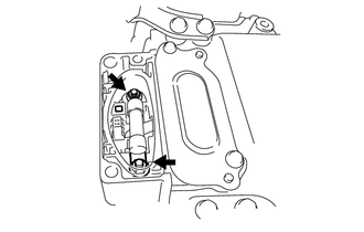
Remove the 2 nuts and high voltage fuse from the inverter with converter assembly.
-
Temporarily install the connector cover assembly with the bolt to prevent any foreign matter or water from entering the inverter with converter assembly.
-
-
REMOVE AIR CLEANER BRACKET
-
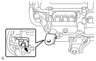
Remove the bolt and air cleaner bracket from the inverter with converter assembly.
-
-
REMOVE AIR CLEANER BRACKET
-
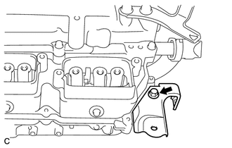
Remove the bolt and air cleaner bracket from the inverter with converter assembly.
-
-
REMOVE NO. 1 INVERTER BRACKET
-
Remove the 2 bolts and No. 1 inverter bracket from the inverter with converter assembly.
-
-
REMOVE NO. 2 INVERTER BRACKET
-
Remove the 2 bolts and No. 2 inverter bracket from the inverter with converter assembly.
-
-
REMOVE NO. 3 INVERTER BRACKET
-
Remove the 2 bolts and No. 3 inverter bracket from the inverter with converter assembly.
-
-
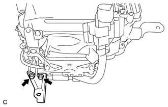
REMOVE NO. 1 MOTOR CABLE BRACKET
-
Remove the 2 bolts and No. 1 motor cable bracket from the inverter with converter assembly.
-
-
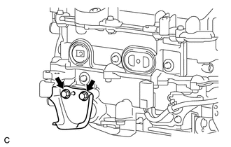
REMOVE NO. 2 MOTOR CABLE BRACKET
-
Remove the 2 bolts and No. 2 motor cable bracket from the inverter with converter assembly.
-
-
REMOVE NO. 1 INVERTER COOLING HOSE
-
Text in Illustration *1 Retainer Release the retainer and disconnect the No. 1 inverter cooling hose from the inverter with converter assembly .
-
Remove the No. 1 inverter cooling hose from the inverter with converter assembly.
-
Put pieces of cloth into the pipes and in the disconnected hoses, or cover the pipes and hoses with plastic bags as shown in the illustration to prevent foreign matter from entering the cooling system and to prevent coolant from spilling near the inverter with converter assembly.
-
-
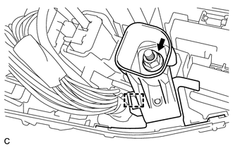
REMOVE NO. 3 ENGINE ROOM WIRE
-
Open the cover.
Note
Do not twist the cover excessively when opening it.
-
Remove the nut and No. 3 engine room wire from the inverter with converter assembly.
-