INVERTER WITH CONVERTER INSTALLATION
CAUTION / NOTICE / HINT
Note
If the inverter with converter assembly has been replaced with a new one, make sure to lock the No. 1 inverter cooling hose retainer.
| *1 | Retainer |
PROCEDURE
-
INSTALL NO. 3 ENGINE ROOM WIRE
-
Temporarily install the No. 3 engine room wire to the inverter with converter assembly with the nut.
-
Tighten the nut.
- Torque:
- 18 N*m { 184 kgf*cm, 13 ft.*lbf }
-
Close the cover.
-
-
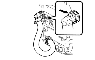
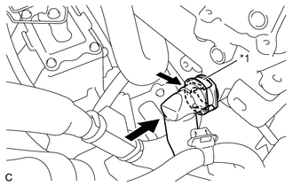
INSTALL NO. 1 INVERTER COOLING HOSE
-
Text in Illustration *1 Retainer Connect the No. 1 inverter cooling hose to the inverter with converter assembly and lock the hose with the retainer.
Note
-
Insert the retainer until a click sound is heard.
-
Pull on the hose to confirm that the hose is securely connected.
-
If there is foreign matter on the union or the O-ring, clean it with water and finger scouring.
-
To prevent foreign matter from entering the cooling system, do not remove the pieces of cloth or plastic bags from the pipes and disconnected hoses until installation.
-
-
-
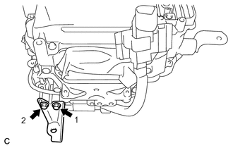
INSTALL NO. 2 MOTOR CABLE BRACKET
-
Install the No. 2 motor cable bracket to the inverter with converter assembly with the 2 bolts.
- Torque:
- 10 N*m { 102 kgf*cm, 7 ft.*lbf }
-
-
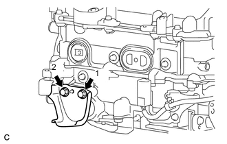
INSTALL NO. 1 MOTOR CABLE BRACKET
-
Install the No. 1 motor cable bracket to the inverter with converter assembly with the 2 bolts.
- Torque:
- 10 N*m { 102 kgf*cm, 7 ft.*lbf }
-
-
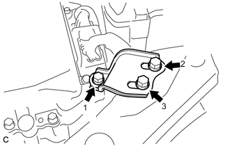
INSTALL NO. 3 INVERTER BRACKET
-
Temporarily install the No. 3 inverter bracket to the inverter with converter assembly with the 2 bolts.
-
Tighten the 2 bolts in the order shown in the illustration.
- Torque:
- 8.5 N*m { 87 kgf*cm, 75 in.*lbf }
-
-
INSTALL NO. 2 INVERTER BRACKET
-
Temporarily install the No. 2 inverter bracket to the inverter with converter assembly with the 2 bolts.
-
Tighten the 2 bolts in the order shown in the illustration.
- Torque:
- 8.5 N*m { 87 kgf*cm, 75 in.*lbf }
-
-
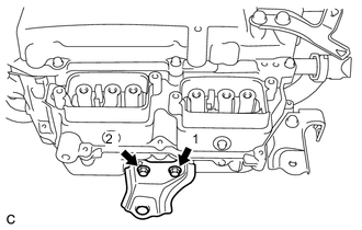
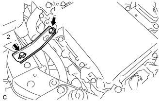
INSTALL NO. 1 INVERTER BRACKET
-
Temporarily install the No. 1 inverter bracket to the inverter with converter assembly with the 2 bolts.
-
Tighten the 2 bolts in the order shown in the illustration.
- Torque:
- 8.5 N*m { 87 kgf*cm, 75 in.*lbf }
-
-
INSTALL AIR CLEANER BRACKET
-
Install the air cleaner bracket to the inverter with converter assembly with the bolt.
- Torque:
- 5.0 N*m { 51 kgf*cm, 44 in.*lbf }
-
-
INSTALL AIR CLEANER BRACKET
-
Install the air cleaner bracket to the inverter with converter assembly with the bolt.
- Torque:
- 5.0 N*m { 51 kgf*cm, 44 in.*lbf }
-
-
INSTALL HIGH VOLTAGE FUSE
CAUTION:
Wear insulated gloves.
Tech Tips
Perform this procedure only when replacement of the high voltage fuse is necessary.
-
Remove the bolt and connector cover assembly from the inverter with converter assembly.
Note
-
Make sure to pull the connector cover assembly straight up, as a connector is connected to the bottom of the cover.
-
Do not allow any foreign matter or water to enter the inverter with converter assembly.
-
-
Install the high voltage fuse to the inverter with converter assembly with 2 new nuts.
- Torque:
- 4.0 N*m { 41 kgf*cm, 35 in.*lbf }
Note
Be sure to use a torque wrench to tighten the nuts.
-
Temporarily install the connector cover assembly with the bolt to prevent any foreign matter or water from entering the inverter with converter assembly.
-
-
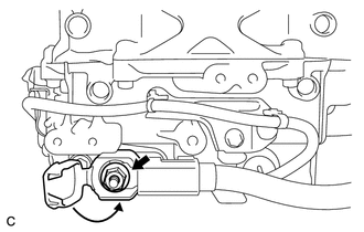
INSTALL INVERTER WITH CONVERTER ASSEMBLY
CAUTION:
Wear insulated gloves.
-
Temporarily install the inverter with converter assembly with the 2 bolts and nut.
Note
-
Since the inverter with converter assembly is very heavy, 2 people are needed to install the inverter with converter assembly. When installing the inverter with converter assembly, do not damage the parts around it.
-
To prevent damage, do not hold the inverter with converter assembly by the connectors.
-
To prevent damage due to static electricity, do not touch the terminals of the disconnected connectors.
-
-
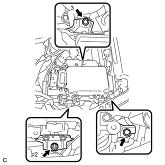
Fully tighten the 2 bolts and nut in the order shown in the illustration.
- Torque:
- 21 N*m { 214 kgf*cm, 15 ft.*lbf }
-
-
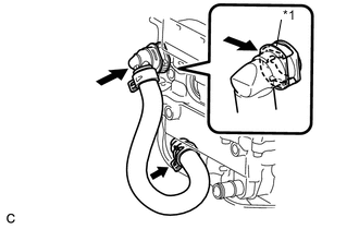
CONNECT NO. 1 INVERTER COOLING HOSE ASSEMBLY
-
Text in Illustration *1 Retainer Connect the No. 1 inverter cooling hose assembly to the inverter with converter assembly and lock the hose with the retainer.
Note
-
Insert the retainer until a click sound is heard.
-
Pull on the hose to confirm that the hose is securely connected.
-
If there is foreign matter on the union or the O-ring, clean it with water and finger scouring.
-
To prevent foreign matter from entering the cooling system, do not remove the pieces of cloth or plastic bags from the pipes and disconnected hoses until installation.
-
-
-
CONNECT NO. 4 INVERTER COOLING HOSE
-
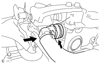
Text in Illustration *1 Retainer Connect the No. 4 inverter cooling hose to the inverter with converter assembly and lock the hose with the retainer.
Note
-
Insert the retainer until a click sound is heard.
-
Pull on the hose to confirm that the hose is securely connected.
-
If there is foreign matter on the union or the O-ring, clean it with water and finger scouring.
-
To prevent foreign matter from entering the cooling system, do not remove the pieces of cloth or plastic bags from the pipes and disconnected hoses until installation.
-
-
-
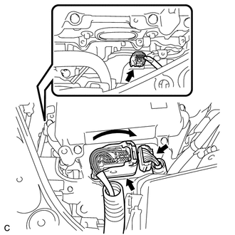
CONNECT NO. 3 ENGINE ROOM WIRE
-
Connect the clamp to the engine room relay block and junction block assembly.
-
Install the No. 3 engine room wire to the engine room relay block and junction block assembly with the nut.
- Torque:
- 8.0 N*m { 82 kgf*cm, 71 in.*lbf }
-
Install the relay block cover to the engine room relay block and junction block assembly.
-
-
CONNECT LOW VOLTAGE CONNECTOR
CAUTION:
Wear insulated gloves.
-
Connect the 3 low voltage connectors and lock the connector with the lock lever.
Note
-
Do not allow any foreign matter or water to enter the inverter with converter assembly.
-
Make sure that the connectors are fully engaged.
-
-
-
REMOVE CONNECTOR COVER ASSEMBLY
-
CONNECT FRAME WIRE
CAUTION:
Wear insulated gloves.
Note
-
Do not damage the terminals, connector housings or inverter with converter assembly during connection.
-
Do not touch the connector waterproofing rubber or terminals.
-
Make sure that the connector is fully engaged.
-
Do not allow any foreign matter or water to enter the inverter with converter assembly.
-
Make sure that the connector does not come out when its body is pulled.
-
Connect the frame wire and wire harness clamp to the inverter with converter assembly.
-
Secure the frame wire to the inverter with converter assembly with the bolt.
- Torque:
- 8.0 N*m { 82 kgf*cm, 71 in.*lbf }
-
-
CONNECT NO. 4 ENGINE WIRE
CAUTION:
Wear insulated gloves.
Note
-
Do not damage the terminals, connector housings or inverter with converter assembly during connection.
-
Do not touch the connector waterproofing rubber or terminals.
-
Make sure that the connector is fully engaged.
-
Do not allow any foreign matter or water to enter the inverter with converter assembly.
-
Make sure that the connector does not come out when its body is pulled.
-
Connect the No. 4 engine wire to the inverter with converter assembly.
-
Connect the wire harness clamp to the No. 2 motor cable bracket.
-
-
INSTALL CONNECTOR COVER ASSEMBLY
CAUTION:
Wear insulated gloves.
-
Install the connector cover assembly to the inverter with converter assembly with the 2 bolts.
- Torque:
- 8.0 N*m { 82 kgf*cm, 71 in.*lbf }
Note
-
Make sure that the interlock is fully engaged.
-
Do not allow any foreign matter or water to enter the inverter with converter assembly.
-
-
INSTALL NO. 3 MOTOR CABLE BRACKET
-
Install the No. 3 motor cable bracket to the inverter with converter assembly with the 2 bolts.
- Torque:
- 10 N*m { 102 kgf*cm, 7 ft.*lbf }
-
Connect the hose clamp to the No. 3 motor cable bracket.
-
-
CONNECT MOTOR CABLE
CAUTION:
Wear insulated gloves.
Note
-
Do not damage the terminals, connector housings or inverter with converter assembly during connection.
-
Do not touch the connector waterproofing rubber or terminals.
-
Do not allow any foreign matter or water to enter the inverter with converter assembly.
-
Connect the motor cable to the inverter with converter assembly.
-
Connect the 3 wire harness clamps.
-
Using an insulated tool, secure the motor cable to the inverter with converter assembly with the 3 bolts.
- Torque:
- 8.0 N*m { 82 kgf*cm, 71 in.*lbf }
Note
-
The terminals should be connected securely.
-
The bolts should be tightened securely.
-
-
INSTALL UPPER INVERTER COVER
CAUTION:
Wear insulated gloves.
-
Install the upper inverter cover (motor cable side) to the inverter with converter assembly with the 2 bolts.
- Torque:
- 8.0 N*m { 82 kgf*cm, 71 in.*lbf }
Note
-
Do not touch the upper inverter cover waterproofing rubber.
-
Visually confirm that the upper inverter cover waterproofing rubber is securely installed before installing the upper inverter cover.
-
Make sure that the interlock is fully engaged.
-
-
CONNECT GENERATOR CABLE
CAUTION:
Wear insulated gloves.
Note
-
Do not damage the terminals, connector housings or inverter with converter assembly during connection.
-
Do not touch the connector waterproofing rubber or terminals.
-
Do not allow any foreign matter or water to enter the inverter with converter assembly.
-
Connect the generator cable to the inverter with converter assembly.
-
Connect the 2 wire harness clamps.
-
Using an insulated tool, secure the generator cable to the inverter with converter assembly with the 3 bolts.
- Torque:
- 8.0 N*m { 82 kgf*cm, 71 in.*lbf }
Note
-
The terminals should be connected securely.
-
The bolts should be tightend securely.
-
-
INSTALL UPPER INVERTER COVER
CAUTION:
Wear insulated gloves.
-
Install the upper inverter cover (generator cable side) to the inverter with converter assembly with the 2 bolts.
- Torque:
- 8.0 N*m { 82 kgf*cm, 71 in.*lbf }
Note
-
Do not touch the upper inverter cover waterproofing rubber.
-
Visually confirm that the upper inverter cover waterproofing rubber is securely installed before installing the upper inverter cover.
-
Make sure that the interlock is fully engaged.
-
-
INSTALL NO. 4 INVERTER BRACKET
-
Temporarily install the No. 4 inverter bracket with the 3 bolts.
-
Tighten the 3 bolts in the order shown in the illustration.
- Torque:
- 10 N*m { 102 kgf*cm, 7 ft.*lbf }
-
-
INSTALL NO. 5 INVERTER BRACKET
-
Temporarily install the No. 5 inverter bracket with the 2 bolts.
-
Tighten the 2 bolts in the order shown in the illustration.
- Torque:
- 10 N*m { 102 kgf*cm, 7 ft.*lbf }
-
-
INSTALL AIR CLEANER CASE SUB-ASSEMBLY
-
INSTALL AIR CLEANER FILTER ELEMENT
-
INSTALL AIR CLEANER CAP SUB-ASSEMBLY
-
INSTALL INLET AIR CLEANER ASSEMBLY
-
INSTALL COOL AIR INTAKE DUCT SEAL
-
INSTALL SERVICE PLUG GRIP
-
ADD COOLANT (for Inverter)
-
INSPECT FOR COOLANT LEAK (for Inverter)