| DTC Code | DTC Name |
|---|---|
| Transmission Control Switch Circuit |
DESCRIPTION
When the shift lever is in S, different ranges can be chosen using the floor shift sequential gate.
PROCEDURE
- Click here
READ VALUE USING GTS (SPORTS MODE)
-
Connect the GTS to the DLC3.
-
Turn the power switch on (IG).
-
Enter the following menus: Powertrain / Hybrid Control / Data List / Sports Mode.
-
Read the value displayed on the GTS.
Result Tester Display Measurement Item/Range Normal Condition Sports Mode Sports shift signal/
ON or OFF
Shift lever in S: ON
Shift lever not in S: OFF
-
Turn the power switch off.
- OKClick here
- NGClick here
-
- Click here
READ VALUE USING GTS (SPORT UP SHIFT SENS STATE / SPORT DWN SHIFT SENS STATE)
-
Connect the GTS to the DLC3.
-
Turn the power switch on (IG).
-
Enter the following menus: Powertrain / Hybrid Control / Data List / Sport Up Shift Sens State/Sport Dwn Shift Sens State.
-
Read the value displayed on the GTS.
Result Tester Display Measurement Item/Range Normal Condition Sport Up Shift Sens State Sports shift UP signal/
ON or OFF
Shift lever in S and held toward +:
ON
Sport Dwn Shift Sens State Sport shift DOWN signal/
ON or OFF
Shift lever in S and held toward -:
ON
-
Turn the power switch off.
- OKClick here
- NGClick here
-
- Click here
CHECK FOR INTERMITTENT PROBLEMS
-
Check for intermittent problems.
-
Move the shift lever to S and jiggle the harness and connector.
-
With the shift lever held toward "+" and then "-", jiggle the harness and connector.
Result Result Proceed to Malfunction does not occur A Malfunction occurs B -
- A
PROCEED TO NEXT SUSPECTED AREA SHOWN IN PROBLEM SYMPTOMS TABLE
- B
REPAIR OR REPLACE MALFUNCTIONING PARTS, COMPONENT AND AREA
-
- Click here
INSPECT LOWER SHIFT LEVER ASSEMBLY (TRANSMISSION CONTROL SWITCH)
-
Disconnect the H33 lower shift lever assembly (transmission control switch) connector.
-

Measure the resistance according to the value(s) in the table below.
Standard Resistance (LHD) Tester Connection Condition Specified Condition 3 - 2 Shift lever in positive (+) Below 1 Ω 3 - 2 Shift lever in S 10 kΩ or higher 1 - 2 1 - 2 Shift lever in negative (-) Below 1 Ω Standard Resistance (RHD) Tester Connection Condition Specified Condition 1 - 2 Shift lever in positive (+) Below 1 Ω 1 - 2 Shift lever in S 10 kΩ or higher 3 - 2 3 - 2 Shift lever in negative (-) Below 1 Ω Table 1. Text in Illustration *a Component without harness connected
(Lower Shift Lever Assembly (Transmission Control Switch))
-
Reconnect the H33 lower shift lever assembly (transmission control switch) connector.
- OKClick here
- NG
REPLACE LOWER SHIFT LEVER ASSEMBLY (TRANSMISSION CONTROL SWITCH) (Click here)
-
- Click here
CHECK HARNESS AND CONNECTOR (LOWER SHIFT LEVER ASSEMBLY (TRANSMISSION CONTROL SWITCH) - HYBRID VEHICLE CONTROL ECU ASSEMBLY)
-
Disconnect the H212 hybrid vehicle control ECU assembly connector.
-
Measure the resistance according to the value(s) in the table below.
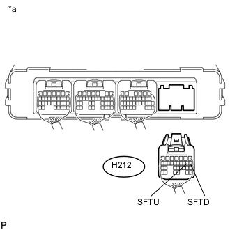
Standard Resistance Tester Connection Condition Specified Condition H212-9 (SFTU) - Body ground Shift lever in positive (+) Below 1 Ω H212-9 (SFTU) - Body ground Shift lever in S 10 kΩ or higher H212-8 (SFTD) - Body ground H212-8 (SFTD) - Body ground Shift lever in negative (-) Below 1 Ω Table 2. Text in Illustration *a Rear view of wire harness connector
(to Hybrid Vehicle Control ECU Assembly)
-
Reconnect the H212 hybrid vehicle control ECU assembly connector.
- OK
REPLACE HYBRID VEHICLE CONTROL ECU ASSEMBLY (Click here)
- NG
REPAIR OR REPLACE HARNESS OR CONNECTOR
-
- Click here
CHECK HARNESS AND CONNECTOR (HYBRID VEHICLE CONTROL ECU ASSEMBLY - LOWER SHIFT LEVER ASSEMBLY (TRANSMISSION CONTROL SWITCH))
-
Disconnect the A79 hybrid vehicle control ECU assembly connector.
-
Disconnect the H33 lower shift lever assembly (transmission control switch) connector.
-
Measure the resistance according to the value(s) in the table below.
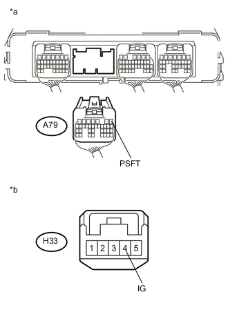
Standard Resistance Tester Connection Condition Specified Condition A79-1 (PSFT) - H33-4 (IG) Always Below 1 Ω A79-1 (PSFT) or H33-4 (IG) - Body ground Always 10 kΩ or higher Table 3. Text in Illustration *a Rear view of wire harness connector
(to Hybrid Vehicle Control ECU Assembly)
*b Front view of wire harness connector
(to Lower Shift Lever Assembly (Transmission Control Switch))
-
Reconnect the H33 lower shift lever assembly (transmission control switch) connector.
-
Reconnect the A79 hybrid vehicle control ECU assembly connector.
- OKClick here
- NG
CHECK POWER SOURCE CIRCUIT
-
- Click here
INSPECT LOWER SHIFT LEVER ASSEMBLY (TRANSMISSION CONTROL SWITCH)
-
Disconnect the H33 lower shift lever assembly (transmission control switch) connector.
-
Measure the resistance according to the value(s) in the table below.
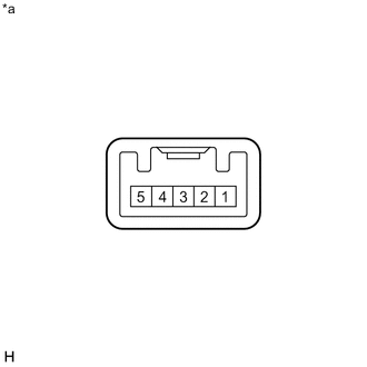
Standard Resistance Tester Connection Condition Specified Condition H33-4 (IG) - H33-5 (S) Shift lever not in S 10 kΩ or higher H33-4 (IG) - H33-5 (S) Shift lever in S Below 1 Ω Table 4. Text in Illustration *a Component without harness connected
(Lower Shift Lever Assembly (Transmission Control Switch))
-
Reconnect the H33 lower shift lever assembly (transmission control switch) connector.
- OKClick here
- NG
REPLACE LOWER SHIFT LEVER ASSEMBLY (TRANSMISSION CONTROL SWITCH) (Click here)
-
- Click here
CHECK HARNESS AND CONNECTOR (LOWER SHIFT LEVER ASSEMBLY (TRANSMISSION CONTROL SWITCH) - HYBRID VEHICLE CONTROL ECU ASSEMBLY)
-
Disconnect the H212 hybrid vehicle control ECU assembly connector.
-
Disconnect the H33 lower shift lever assembly (transmission control switch) connector.
-
Measure the resistance according to the value(s) in the table below.
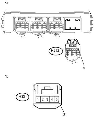
Standard Resistance Tester Connection Condition Specified Condition H212-1 (M) - H33-5 (S) Always Below 1 Ω H212-1 (M) or H33-5 (S) - Body ground Always 10 kΩ or higher Table 5. Text in Illustration *a Rear view of wire harness connector
(to Hybrid Vehicle Control ECU Assembly)
*b Front view of wire harness connector
(to Lower Shift Lever Assembly (Transmission Control Switch))
-
Turn the power switch on (IG)
-
Measure the voltage according to the value(s) in the table below.
Standard Voltage Tester Connection Condition Specified Condition H212-1 (M) - H33-5 (S) Power switch on (IG) Below 1 V -
Turn the power switch off.
-
Reconnect the H33 lower shift lever assembly (transmission control switch) connector.
-
Reconnect the H212 hybrid vehicle control ECU assembly connector.
- OK
REPLACE HYBRID VEHICLE CONTROL ECU ASSEMBLY (Click here)
- NG
REPAIR OR REPLACE HARNESS OR CONNECTOR
-