Info Added 2017-08-02
| DTC Code | DTC Name |
|---|---|
| P0560-117 | System Voltage |
DESCRIPTION
-
Battery power is constantly supplied to the BATT terminal of the hybrid vehicle control ECU assembly to allow DTCs and freeze frame data to be retained in memory even though the power switch is turned off. The back-up power is supplied even when the power switch is off.
| DTC No. | INF Code | DTC Detection Condition | Trouble Area |
|---|---|---|---|
| P0560 | 117 | Malfunction in the hybrid vehicle control ECU assembly back-up power source circuit (1 trip detection logic) |
|
| DTC No. | Data List |
|---|---|
| P0560-117 | +B |
CAUTION / NOTICE / HINT
After the repair, clear the DTCs and perform the following procedure to check that DTCs are not output.
-
Turn the power switch ON (IG) and wait for a few seconds.
PROCEDURE
- Click here
CHECK CONNECTOR CONNECTION CONDITION (HYBRID VEHICLE CONTROL ECU ASSEMBLY CONNECTOR)
-
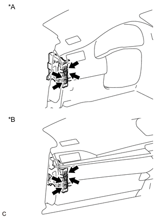
Check the connector connections and contact pressure of the relevant terminals for the hybrid vehicle control ECU assembly connectors (Click here).
Table 2. Text in Illustration *A for LHD *B for RHD OK The connectors are connected securely and there are no contact pressure problems.
- OKClick here
- NG
CONNECT SECURELY
-
- Click here
CHECK HARNESS AND CONNECTOR (HYBRID VEHICLE CONTROL ECU - ECU-B NO. 1 FUSE)
-
Turn the power switch off.
-
Measure the voltage according to the value(s) in the table below.
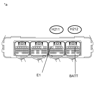
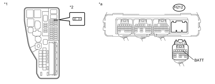
Table 3. Text in Illustration *a Component with harness connected
(Hybrid Vehicle Control ECU Assembly)
Standard Voltage Tester Connection Switch Condition Specified Condition H212-3 (BATT) - H211-6 (E1) power switch off 11 to 14 V
- OK
REPLACE HYBRID VEHICLE CONTROL ECU ASSEMBLY (Click here)
- NGClick here
-
- Click here
CHECK FUSE (ECU-B NO. 1)
-
Remove the ECU-B NO. 1 fuse from the engine room relay block and junction block assembly.
-
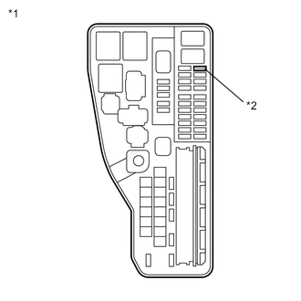
Measure the resistance according to the value(s) in the table below.
Standard Resistance Tester Connection Switch Condition Specified Condition ECU-B NO. 1fuse Power switch off Below 1 Ω Table 4. Text in Illustration *1 Engine Room Relay Block and Junction Block Assembly *2 ECU-B NO. 1 Fuse
- OKClick here
- NG
REPLACE FUSE (ECU-B NO. 1)
-
- Click here
CHECK HARNESS AND CONNECTOR (ECU-B NO. 1 FUSE - AUXILIARY BATTERY POSITIVE TERMINAL)
-
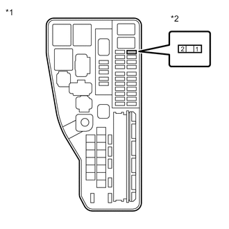
Remove the ECU-B NO. 1 fuse from the engine room relay block and junction block assembly.
-
Disconnect the cable from the negative (-) auxiliary battery terminal.
-
Disconnect the cable from the positive (+) auxiliary battery terminal.
-
Measure the resistance according to the value(s) in the table below.
Standard Resistance Tester Connection Switch Condition Specified Condition 1 - Auxiliary battery positive (+) cable Power switch off Below 1 Ω 1 - Body ground Power switch off 10 kΩ or higher Table 5. Text in Illustration *1 Engine Room Relay Block and Junction Block Assembly *2 ECU-B NO. 1 Fuse -
Connect the cable to the positive (+) auxiliary battery terminal.
-
Connect the cable to the negative (-) auxiliary battery terminal.
-
Install the ECU-B NO. 1 fuse.
- OKClick here
- NG
REPAIR OR REPLACE HARNESS OR CONNECTOR
-
- Click here
CHECK HARNESS AND CONNECTOR (ECU-B NO. 1 FUSE - HYBRID VEHICLE CONTROL)
-
Remove the ECU-B NO. 1 fuse from the engine room relay block and junction block assembly.
-
Disconnect the H212 hybrid vehicle control ECU assembly connector.
-
Measure the resistance according to the value(s) in the table below.
Table 6. Text in Illustration *1 Engine Room Relay Block and Junction Block Assembly *2 ECU-B NO. 1 Fuse *a Rear view of wire harness connector
(to Hybrid Vehicle Control ECU Assembly)
- - Standard Resistance Tester Connection Switch Condition Specified Condition 2 (ECU-B NO. 1 fuse terminal) - H212-3 (BATT) power switch off Below 1 Ω -
Reconnect the H212 hybrid vehicle control ECU assembly connector.
-
Install the ECU-B NO. 1 fuse.
- OK
REPLACE HYBRID VEHICLE CONTROL ECU ASSEMBLY (Click here)
- NG
REPAIR OR REPLACE HARNESS OR CONNECTOR
-