HYBRID CONTROL SYSTEM, Diagnostic DTC:P1CAC-200, P1CAF-792, P1CB2-793
Info Added 2017-08-02 ![]()
| DTC Code | DTC Name |
|---|---|
| P1CAC-200 | Generator Position Sensor Angle Malfunction |
| P1CAF-792 | Generator Position Sensor REF Signal Cycle Malfunction |
| P1CB2-793 | Generator Position Sensor REF Signal Stop Malfunction |
DESCRIPTION
The MG ECU located in the inverter with converter assembly monitors its internal operation and detects the following malfunctions.
| DTC No. | INF Code | DTC Detection Condition | Trouble Area |
|---|---|---|---|
| P1CAC | 200 | The difference between the resolver angle for control and estimated resolver angle exceeds the allowable value. |
|
| P1CAF | 792 | Resolver REF signal cycle error | |
| P1CB2 | 793 | Resolver REF signal oscillation stop error |
WIRING DIAGRAM
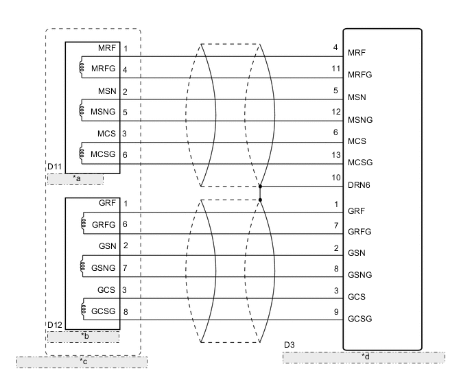
| *a | Motor Resolver |
| *b | Generator Resolver |
| *c | Hybrid Vehicle Transaxle Assembly |
| *d | Inverter with Converter Assembly (MG ECU) |
CAUTION / NOTICE / HINT
CAUTION:
-
Before inspecting the high-voltage system or disconnecting the low voltage connector of the inverter with converter assembly, take safety precautions such as wearing insulated gloves and removing the service plug grip to prevent electrical shocks. After removing the service plug grip, put it in your pocket to prevent other technicians from accidentally reconnecting it while you are working on the high-voltage system.
-
After removing the service plug grip, wait for at least 10 minutes before touching any of the high-voltage connectors or terminals. After waiting for 10 minutes, check the voltage at the terminals in the inspection point in the inverter with converter assembly. The voltage should be 0 V before beginning work Click here.
Tech Tips
Waiting for at least 10 minutes is required to discharge the high-voltage capacitor inside the inverter with converter assembly.
Note
After turning the power switch off, waiting time may be required before disconnecting the cable from the negative (-) auxiliary battery terminal. Therefore, make sure to read the disconnecting the cable from the negative (-) auxiliary battery terminal notices before proceeding with work Click here.
PROCEDURE
-
CHECK DTC OUTPUT (HYBRID CONTROL)
-
Connect the GTS to the DLC3.
-
Turn the power switch on (IG).
-
Enter the following menus: Powertrain / Hybrid Control / Trouble Codes.
-
Check for DTCs.
Result Result Proceed to P1CAC-200, P1CAF-792 or P1CB2-793 only is output, or DTCs except the ones in the table below are also output. A Any of the following DTCs are also output. B DTC No. Relevant Diagnosis P0A3F-243 Drive Motor "A" Position Sensor Circuit P0A4B-253 Generator Position Sensor Circuit P0A4C-513 Generator Position Sensor Circuit Range / Performance P0A4D-255 Generator Position Sensor Circuit Low -
Turn the power switch off.
B 
GO TO DTC CHART (HYBRID CONTROL SYSTEM) Click here
A 
-
-
CHECK CONNECTOR CONNECTION CONDITION (INVERTER WITH CONVERTER ASSEMBLY CONNECTOR)
CAUTION:
Be sure to wear insulated gloves.
-
Check that the service plug grip is not installed.
Note
After removing the service plug grip, do not turn the power switch on (READY), unless instructed by the repair manual because this may cause a malfunction.
-
Check the connector connections and contact pressure of the low voltage connectors of the inverter with converter assembly Click here.
Note
Before disconnecting the connector, confirm that it is properly connected by checking that the locking claws are engaged and that the connector does not pull out.
OK The connectors are connected securely and there are no contact pressure problems. Tech Tips
When connecting the connector, insert it with the locking lever in the raised position. Rotate the lever downward and make sure that the connector is pulled into its socket. When the locking lever is in its fully closed position, a click will be heard as its locking claws engage. After the click is heard, pull up on the connector to confirm that it is properly connected.
NG
CONNECT SECURELY
OK
-
-
CHECK HARNESS AND CONNECTOR (INVERTER WITH CONVERTER ASSEMBLY - GENERATOR RESOLVER)
CAUTION:
Be sure to wear insulated gloves.
-
Check that the service plug grip is not installed.
Note
After removing the service plug grip, do not turn the power switch on (READY), unless instructed by the repair manual because this may cause a malfunction.
-
Disconnect the D3 inverter with converter assembly connector.
-
Connect the cable to the negative (-) auxiliary battery terminal.
-
Turn the power switch on (IG).
-
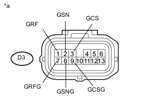
Text in Illustration *a Front view of wire harness connector
(to Inverter with Converter Assembly)
Measure the voltage according to the value(s) in the table below.
Standard Voltage Tester Connection Condition Specified Condition D3-1 (GRF) - Body ground Power switch on (IG) Below 1 V D3-7 (GRFG) - Body ground Power switch on (IG) Below 1 V D3-2 (GSN) - Body ground Power switch on (IG) Below 1 V D3-8 (GSNG) - Body ground Power switch on (IG) Below 1 V D3-3 (GCS) - Body ground Power switch on (IG) Below 1 V D3-9 (GCSG) - Body ground Power switch on (IG) Below 1 V Note
Turning the power switch on (IG) with the low voltage connector of the inverter with converter assembly disconnected causes other DTCs to be stored. Clear the DTCs after performing this inspection.
-
Turn the power switch off.
-
Disconnect the cable from the negative (-) auxiliary battery terminal.
-
Reconnect the D3 inverter with converter assembly connector.
NG
REPAIR OR REPLACE HARNESS OR CONNECTOR
OK
-
-
CHECK GENERATOR RESOLVER
CAUTION:
Be sure to wear insulated gloves.
-
Check that the service plug grip is not installed.
Note
After removing the service plug grip, do not turn the power switch on (READY), unless instructed by the repair manual because this may cause a malfunction.
-
Disconnect the D3 inverter with converter assembly connector.
-
Text in Illustration *a Front view of wire harness connector
(to Inverter with Converter Assembly)
Measure the resistance according to the value(s) in the table below.
Standard Resistance Tester Connection Condition Specified Condition D3-1 (GRF) - D3-7 (GRFG) Power switch off 4.2 to 12.5 Ω D3-2 (GSN) - D3-8 (GSNG) Power switch off 9.8 to 20.1 Ω D3-3 (GCS) - D3-9 (GCSG) Power switch off 9.8 to 20.1 Ω Tech Tips
To correct the variation of the measured resistance due to temperature, use the following formula to calculate the resistance at 20°C (68°F).
R20 = Rt / {1 + 0.00393 X (T - 20)}
The calculation is based on the following:
R20: Resistance at 20°C (68°F) (mΩ)
Rt: Measured resistance (mΩ)
T: Temperature when the resistance is measured (°C (°F).)
Standard Resistance (Check for Short) Tester Connection Condition Specified Condition D3-1 (GRF) or D3-7 (GRFG) - Body ground and other terminals Power switch off 1 MΩ or higher D3-2 (GSN) or D3-8 (GSNG) - Body ground and other terminals Power switch off 1 MΩ or higher D3-3 (GCS) or D3-9 (GCSG) - Body ground and other terminals Power switch off 1 MΩ or higher -
Reconnect the D3 inverter with converter assembly connector.
NG 
CHECK CONNECTOR CONNECTION CONDITION (GENERATOR RESOLVER CONNECTOR) Click here
OK
-
-
CHECK HARNESS AND CONNECTOR (INVERTER WITH CONVERTER ASSEMBLY - MOTOR RESOLVER)
CAUTION:
Be sure to wear insulated gloves.
-
Check that the service plug grip is not installed.
Note
After removing the service plug grip, do not turn the power switch on (READY), unless instructed by the repair manual because this may cause a malfunction.
-
Disconnect the D3 inverter with converter assembly connector.
-
Connect the cable to the negative (-) auxiliary battery terminal.
-
Turn the power switch on (IG).
-
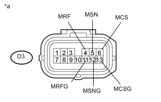
Text in Illustration *a Front view of wire harness connector
(to Inverter with Converter Assembly)
Measure the voltage according to the value(s) in the table below.
Standard Voltage Tester Connection Condition Specified Condition D3-4 (MRF) - Body ground Power switch on (IG) Below 1 V D3-11 (MRFG) - Body ground Power switch on (IG) Below 1 V D3-5 (MSN) - Body ground Power switch on (IG) Below 1 V D3-12 (MSNG) - Body ground Power switch on (IG) Below 1 V D3-6 (MCS) - Body ground Power switch on (IG) Below 1 V D3-13 (MCSG) - Body ground Power switch on (IG) Below 1 V Note
Turning the power switch on (IG) with the low voltage connector of the inverter with converter assembly disconnected causes other DTCs to be stored. Clear the DTCs after performing this inspection.
-
Turn the power switch off.
-
Disconnect the cable from the negative (-) auxiliary battery terminal.
-
Reconnect the D3 inverter with converter assembly connector.
NG
REPAIR OR REPLACE HARNESS OR CONNECTOR
OK
-
-
CHECK MOTOR RESOLVER
CAUTION:
Be sure to wear insulated gloves.
-
Check that the service plug grip is not installed.
Note
After removing the service plug grip, do not turn the power switch on (READY), unless instructed by the repair manual because this may cause a malfunction.
-
Disconnect the D3 inverter with converter assembly connector.
-
Text in Illustration *a Front view of wire harness connector
(to Inverter with Converter Assembly)
Measure the resistance according to the value(s) in the table below.
Standard Resistance Tester Connection Condition Specified Condition D3-4 (MRF) - D3-11 (MRFG) Power switch off 4.2 to 12.5 Ω D3-5 (MSN) - D3-12 (MSNG) Power switch off 9.8 to 20.1 Ω D3-6 (MCS) - D3-13 (MCSG) Power switch off 9.8 to 20.1 Ω Tech Tips
To correct the variation of the measured resistance due to temperature, use the following formula to calculate the resistance at 20°C (68°F).
R20 = Rt / {1 + 0.00393 X (T - 20)}
The calculation is based on the following:
R20: Resistance at 20°C (68°F) (mΩ)
Rt: Measured resistance (mΩ)
T: Temperature when the resistance is measured (°C (°F).)
Standard Resistance (Check for Short) Tester Connection Condition Specified Condition D3-4 (MRF) or D3-11 (MRFG) - Body ground and other terminals Power switch off 1 MΩ or higher D3-5 (MSN) or D3-12 (MSNG) - Body ground and other terminals Power switch off 1 MΩ or higher D3-6 (MCS) or D3-13 (MCSG) - Body ground and other terminals Power switch off 1 MΩ or higher -
Reconnect the D3 inverter with converter assembly connector.
NG
CHECK CONNECTOR CONNECTION CONDITION (MOTOR RESOLVER CONNECTOR) Click here
OK
-
-
CHECK CONNECTOR CONNECTION CONDITION (GENERATOR RESOLVER CONNECTOR)
-
Check the connection of the generator resolver connector.
OK The connector is connected securely and there are no contact problems.
NG
CONNECT SECURELY
OK
-
-
CHECK CONNECTOR CONNECTION CONDITION (MOTOR RESOLVER CONNECTOR)
-
Check the connection of the motor resolver connector.
OK The connector is connected securely and there are no contact problems.
OK
REPLACE INVERTER WITH CONVERTER ASSEMBLY Click here
NG
CONNECT SECURELY
-
-
CHECK CONNECTOR CONNECTION CONDITION (GENERATOR RESOLVER CONNECTOR)
-
Check the connection of the generator resolver connector.
OK The connector is connected securely and there are no contact problems.
NG
CONNECT SECURELY
OK
-
-
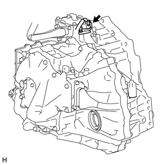
INSPECT HYBRID VEHICLE TRANSAXLE ASSEMBLY (GENERATOR RESOLVER)
-
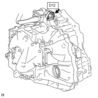
Disconnect the D12 generator resolver connector.
-
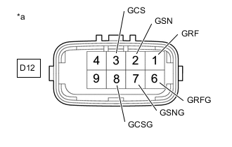
*a Component without harness connected
(Generator Resolver (Hybrid Vehicle Transaxle Assembly))
Measure the resistance according to the value(s) in the table below.
Standard Resistance Tester Connection Condition Specified Condition D12-1 (GRF) - D12-6 (GRFG) Power switch off 5.8 to 11.8 Ω D12-2 (GSN) - D12-7 (GSNG) Power switch off 11.7 to 17.7 Ω D12-3 (GCS) - D12-8 (GCSG) Power switch off 11.7 to 17.7 Ω Tech Tips
To correct the variation of the measured resistance due to temperature, use the following formula to calculate the resistance at 20°C (68°F).
R20 = Rt / {1 + 0.00393 X (T - 20)}
The calculation is based on the following:
R20: Resistance at 20°C (68°F) (mΩ)
Rt: Measured resistance (mΩ)
T: Temperature when the resistance is measured (°C (°F).)
Standard Resistance (Check for Short) Tester Connection Condition Specified Condition D12-1 (GRF) - Body ground and other terminals (except 6 (GRFG)) Power switch off 1 MΩ or higher D12-6 (GRFG) - Body ground and other terminals (except 1 (GRF)) Power switch off 1 MΩ or higher D12-2 (GSN) - Body ground and other terminals (except 7 (GSNG)) Power switch off 1 MΩ or higher D12-7 (GSNG) - Body ground and other terminals (except 2 (GSN)) Power switch off 1 MΩ or higher D12-3 (GCS) - Body ground and other terminals (except 8 (GCSG)) Power switch off 1 MΩ or higher D12-8 (GCSG) - Body ground and other terminals (except 3 (GCS)) Power switch off 1 MΩ or higher Tech Tips
The generator resolver is not available as a supply part. If it requires replacement, replace the hybrid vehicle transaxle assembly.
-
Reconnect the D12 generator resolver connector.
OK
REPAIR OR REPLACE HARNESS OR CONNECTOR
NG
REPLACE HYBRID VEHICLE TRANSAXLE ASSEMBLY Click here
-
-
CHECK CONNECTOR CONNECTION CONDITION (MOTOR RESOLVER CONNECTOR)
-
Check the connection of the motor resolver connector.
OK The connector is connected securely and there are no contact problems.
NG
CONNECT SECURELY
OK
-
-
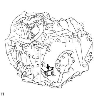
INSPECT HYBRID VEHICLE TRANSAXLE ASSEMBLY (MOTOR RESOLVER)
-
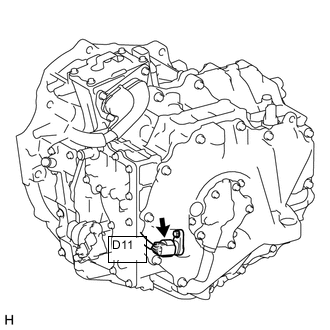
Disconnect the D11 motor resolver connector.
-
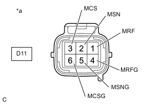
*a Component without harness connected
(Motor Resolver (Hybrid Vehicle Transaxle Assembly))
Measure the resistance according to the value(s) in the table below.
Standard Resistance Tester Connection Condition Specified Condition D11-1 (MRF) - D11-4 (MRFG) Power switch off 5.8 to 11.8 Ω D11-2 (MSN) - D11-5 (MSNG) Power switch off 11.7 to 17.7 Ω D11-3 (MCS) - D11-6 (MCSG) Power switch off 11.7 to 17.7 Ω Tech Tips
To correct the variation of the measured resistance due to temperature, use the following formula to calculate the resistance at 20°C (68°F).
R20 = Rt / {1 + 0.00393 X (T - 20)}
The calculation is based on the following:
R20: Resistance at 20°C (68°F) (mΩ)
Rt: Measured resistance (mΩ)
T: Temperature when the resistance is measured (°C (°F).)
Standard Resistance (Check for Short) Tester Connection Condition Specified Condition D11-1 (MRF) - Body ground and other terminals (except 4 (MRFG)) Power switch off 1 MΩ or higher D11-4 (MRFG) - Body ground and other terminals (except 1 (MRF)) Power switch off 1 MΩ or higher D11-2 (MSN) - Body ground and other terminals (except 5 (MSNG)) Power switch off 1 MΩ or higher D11-5 (MSNG) - Body ground and other terminals (except 2 (MSN)) Power switch off 1 MΩ or higher D11-3 (MCS) - Body ground and other terminals (except 6 (MCSG)) Power switch off 1 MΩ or higher D11-6 (MCSG) - Body ground and other terminals (except 3 (MCS)) Power switch off 1 MΩ or higher Tech Tips
The motor resolver is not available as a supply part. If it requires replacement, replace the hybrid vehicle transaxle assembly.
-
Reconnect the D11 motor resolver connector.
OK
REPAIR OR REPLACE HARNESS OR CONNECTOR
NG
REPLACE HYBRID VEHICLE TRANSAXLE ASSEMBLY Click here
-