HYBRID CONTROL SYSTEM, Diagnostic DTC:P0851-775
| DTC Code | DTC Name |
|---|---|
| P0851-775 | Park / Neutral Switch Input Circuit Low |
DESCRIPTION
Refer to the description for DTC P0705-757 Click here.
| DTC No. | INF Code | DTC Detection Condition | Trouble Area |
|---|---|---|---|
| P0851 | 775 | N signal line malfunction |
|
WIRING DIAGRAM
Refer to the wiring diagram for DTC P0705-757 Click here.
PROCEDURE
-
CHECK DTC OUTPUT (HYBRID CONTROL)
-
Connect the GTS to the DLC3.
-
Turn the power switch on (IG).
-
Enter the following menus: Powertrain / Hybrid Control / Trouble Codes.
-
Check for DTCs.
Result Result Proceed to P0851-775 only is output. A P0705-757 is also output. B -
Turn the power switch off.
B 
GO TO DTC CHART (P0705-757) Click here
A 
-
-
CHECK SHIFT LEVER POSITION SENSOR
-
Turn the power switch on (IG).
-
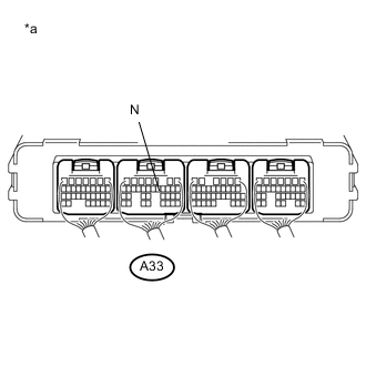
Text in Illustration *a Component with harness connected
(Power Management Control ECU)
Measure the voltage according to the value(s) in the table below.
Standard Voltage Tester Connection Condition Specified Condition A33-12 (N) - Body ground Power switch on (IG)
Shift lever in N
11 to 14 V A33-12 (N) - Body ground Power switch on (IG)
Shift lever in any position except N
1.2 to 2.8 V -
Turn the power switch off.
NG 
CHECK HARNESS AND CONNECTOR (POWER SOURCE CIRCUIT) Click here
OK
-
-
CHECK FOR INTERMITTENT PROBLEMS
OK
REPLACE POWER MANAGEMENT CONTROL ECU Click here
NG
REPAIR OR REPLACE MALFUNCTIONING PARTS, COMPONENT AND AREA
-
CHECK HARNESS AND CONNECTOR (POWER SOURCE CIRCUIT)
-
Disconnect the D10 shift lever position sensor connector.
-
Turn the power switch on (IG).
-
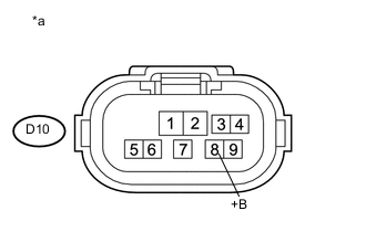
Text in Illustration *a Front view of wire harness connector
(to Shift Lever Position Sensor)
Measure the voltage according to the value(s) in the table below.
Standard Voltage Tester Connection Condition Specified Condition D10-8 (+B) - Body ground Power switch on (IG) 11 to 14 V Note
Turning the power switch on (IG) with the shift lever position sensor connector disconnected causes other DTCs to be stored. Clear the DTCs after performing this inspection.
-
Turn the power switch off.
-
Reconnect the D10 shift lever position sensor connector.
NG
REPAIR OR REPLACE POWER SOURCE CIRCUIT
OK
-
-
INSPECT SHIFT LEVER POSITION SENSOR
-
Disconnect the shift lever position sensor connector.
-
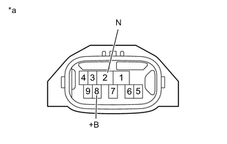
Text in Illustration *a Component without harness connected
(Shift Lever Position Sensor)
Measure the resistance according to the value(s) in the table below.
Standard Resistance Tester Connection Condition Specified Condition 8 (+B) - 2 (N) Shift lever in N Below 1 Ω 8 (+B) - 2 (N) Shift lever in any position except N 4.2 to 5.2 kΩ -
Reconnect the shift lever position sensor connector.
OK
REPAIR OR REPLACE HARNESS OR CONNECTOR
NG
REPLACE SHIFT LEVER POSITION SENSOR Click here
-