| DTC Code | DTC Name |
|---|---|
| P0705-757 | Transmission Range Sensor Circuit |
DESCRIPTION
The shift lever position sensor can send 8 different switch signals to the power management control ECU. The power management control ECU uses the signals to detect the shift lever position (P, R, N or D). The power management control ECU also uses this information to determine the intended direction of travel (forward or reverse).
| DTC No. | INF Code | DTC Detection Condition | Trouble Area |
|---|---|---|---|
| P0705 | 757 | Logical inconsistency in shift sensor output values |
|
PROCEDURE
- Click here
READ VALUE USING GTS (SHIFT SENSOR SW)
-
Connect the GTS to the DLC3.
-
Turn the power switch on (IG).
-
Enter the following menus: Powertrain / Hybrid Control / Data List / Shift Sensor SW - P, Shift Sensor SW - R, Shift Sensor SW - N, Shift Sensor SW - D, Shift Sensor SW - FD, Shift Sensor SW - RV, Shift Sensor SW - MJ.
-
While slowly moving the shift lever from P to D, then back to P, read the Data List (Shift Sensor SW) displayed on the GTS.
Tip:Be sure to move the shift lever slowly.
Result ECU Data List Shift Position P R N D, S Shift Sensor SW-P ON OFF OFF OFF Shift Sensor SW-R OFF ON OFF OFF Shift Sensor SW-N OFF OFF ON OFF Shift Sensor SW-D OFF OFF OFF ON Shift Sensor SW-FD OFF OFF OFF ON Shift Sensor SW-RV OFF ON OFF OFF Shift Sensor SW-MJ ON ON ON ON -
Check for DTCs.
OK DTC P0705-757 is not output. -
Turn the power switch off.
- OKClick here
- NGClick here
-
- Click here
CHECK FOR INTERMITTENT PROBLEMS
- OK
REPLACE POWER MANAGEMENT CONTROL ECU (Click here)
- NG
REPAIR OR REPLACE MALFUNCTIONING PARTS, COMPONENT AND AREA
- OK
- Click here
CHECK SHIFT LEVER POSITION SENSOR
-
Turn the power switch on (IG).
-
Measure the voltage according to the value(s) in the table below.
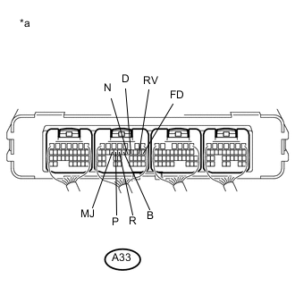
Standard Voltage Tester Connection Condition Specified Condition A33-15 (P) - Body ground Power switch on (IG)
Shift lever in P
11 to 14 V Power switch on (IG)
Shift lever in any position except P
0 to 1.5 V A33-14 (R) - Body ground Power switch on (IG)
Shift lever in R
11 to 14 V Power switch on (IG)
Shift lever in any position except R
0 to 1.5 V A33-12 (N) - Body ground Power switch on (IG)
Shift lever in N
11 to 14 V Power switch on (IG)
Shift lever in any position except N
1.2 to 2.8 V A33-11 (D) - Body ground Power switch on (IG)
Shift lever in D or S
11 to 14 V Power switch on (IG)
Shift lever in any position except D or S
0 to 1.5 V A33-13 (B) - Body ground Power switch on (IG)
Any position
0 to 1.5 V A33-16 (MJ) - Body ground Power switch on (IG)
Shift lever in P, R, N, D or S
11 to 14 V A33-8 (FD) - Body ground Power switch on (IG)
Shift lever in D or S
11 to 14 V Power switch on (IG)
Shift lever in any position except D or S
0 to 1.5 V A33-9 (RV) - Body ground Power switch on (IG)
Shift lever in R
11 to 14 V Power switch on (IG)
Shift lever in any position except R
0 to 1.5 V Table 1. Text in Illustration *a Component with harness connected
(Power Management Control ECU)
-
Turn the power switch off.
- OK
REPLACE POWER MANAGEMENT CONTROL ECU (Click here)
- NGClick here
-
- Click here
CHECK HARNESS AND CONNECTOR (POWER SOURCE CIRCUIT)
-
Disconnect the D65 shift lever position sensor connector.
-
Turn the power switch on (IG).
-
Measure the voltage according to the value(s) in the table below.
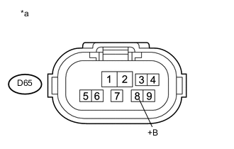
Standard Voltage Tester Connection Condition Specified Condition D65-8 (+B) - Body ground Power switch on (IG) 11 to 14 V Table 2. Text in Illustration *a Front view of wire harness connector
(to Shift Lever Position Sensor)
Note:Turning the power switch on (IG) with the shift lever position sensor connector disconnected causes other DTCs to be stored. Clear the DTCs after performing this inspection.
-
Turn the power switch off.
-
Reconnect the D65 shift lever position sensor connector.
- OKClick here
- NG
REPAIR OR REPLACE POWER SOURCE CIRCUIT
-
- Click here
INSPECT SHIFT LEVER POSITION SENSOR
-
Disconnect the shift lever position sensor connector.
-
Measure the resistance according to the value(s) in the table below.
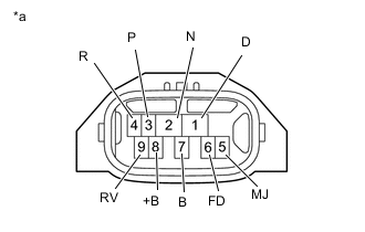
Standard Resistance (Check for Open) Tester Connection Condition Specified Condition 8 (+B) - 3 (P) Shift lever in P Below 1 Ω 8 (+B) - 5 (MJ) 8 (+B) - 4 (R) Shift lever in R Below 1 Ω 8 (+B) - 5 (MJ) 8 (+B) - 9 (RV) 8 (+B) - 2 (N) Shift lever in N Below 1 Ω 8 (+B) - 5 (MJ) 8 (+B) - 1 (D) Shift lever in D or S Below 1 Ω 8 (+B) - 6 (FD) 8 (+B) - 5 (MJ) Standard Resistance (Check for Short) Tester Connection Condition Specified Condition 8 (+B) or 3 (P) - Body ground and other terminals Shift lever in P 10 kΩ or higher*1 8 (+B) or 5 (MJ) - Body ground and other terminals 8 (+B) or 4 (R) - Body ground and other terminals Shift lever in R 10 kΩ or higher*1 8 (+B) or 5 (MJ) - Body ground and other terminals 8 (+B) or 9 (RV) - Body ground and other terminals 8 (+B) or 2 (N) - Body ground and other terminals Shift lever in N 10 kΩ or higher 8 (+B) or 5 (MJ) - Body ground and other terminals 8 (+B) or 1 (D) - Body ground and other terminals Shift lever in D or S 10 kΩ or higher*1 8 (+B) or 6 (FD) - Body ground and other terminals 8 (+B) or 5 (MJ) - Body ground and other terminals Table 3. Text in Illustration *a Component without harness connected
(Shift Lever Position Sensor)
Note:*1: The resistance between terminals 8 (+B) and 2 (N) should be between 4.2 and 5.2 kΩ.
-
Reconnect the shift lever position sensor connector.
- OK
REPAIR OR REPLACE HARNESS OR CONNECTOR
- NG
REPLACE SHIFT LEVER POSITION SENSOR (Click here)
-