HYBRID CONTROL SYSTEM, Diagnostic DTC:P2532-772
| DTC Code | DTC Name |
|---|---|
| P2532-772 | Ignition Switch Run Position Circuit High |
DESCRIPTION
The hybrid vehicle control ECU assembly monitors the IGSW signals sent from the certification ECU (smart key ECU assembly) and detects a malfunction.
Tech Tips
If DTC P2532-772 is stored, the vehicle will turn off.
| DTC No. | INF Code | DTC Detection Condition | Trouble Area |
|---|---|---|---|
| P2532 | 772 | When communication is lost from ECU that has IG1 circuit power supply and power is supplied to IG2 terminal. |
|
WIRING DIAGRAM
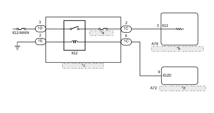
| *a | ECU-IG2 NO. 3 |
| *b | Hybrid Vehicle Control ECU Assembly |
| *c | No. 1 Integration Relay |
| *d | Certification ECU (Smart Key ECU Assembly) |
PROCEDURE
-
CHECK DTC OUTPUT (HYBRID CONTROL)
-
Connect the GTS to the DLC3.
-
Turn the power switch on (IG).
-
Enter the following menus: Powertrain / Hybrid Control / Trouble Codes.
-
Check for DTCs.
Result Result Proceed to P2532-772 only is output. A DTCs except P2532-772 are output. B -
Turn the power switch off.
B 
CHECK FOR INTERMITTENT PROBLEMS Click here
A 
-
-
READ VALUE USING GTS (CAN BUS CHECK))
-
Connect the GTS to the DLC3.
-
Turn the power switch on (IG).
-
Enter the following menus: CAN Bus Check.
Result Result Proceed to All of the ECUs and sensors that are currently connected to the CAN communication system are displayed. A None of the ECUs and sensors that are currently connected to the CAN communication system are displayed, or some of them are not displayed. B -
Turn the power switch off.
B 
GO TO CAN COMMUNICATION SYSTEM
A
-
-
CHECK HARNESS AND CONNECTOR (+B SHORT)
-
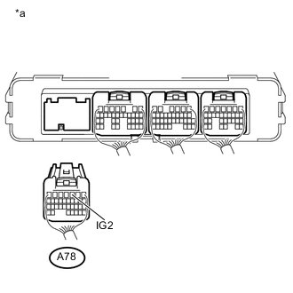
Text in Illustration *a Rear view of wire harness connector
(to Hybrid Vehicle Control ECU Assembly)
Disconnect connector A78 from the hybrid vehicle control ECU assembly.
-
Measure the voltage according to the value(s) in the table below.
Standard Voltage Tester Connection Switch Condition Specified Condition A78-3 (IG2) - Body ground Power switch off 1 V or less Result Result Proceed to NG A OK B -
Reconnect the A78 hybrid vehicle control ECU assembly connector.
B
REPLACE HYBRID VEHICLE CONTROL ECU ASSEMBLY Click here
A
-
-
INSPECT INTEGRATION NO.1 RELAY (IG2)
NG
REPLACE NO. 1 INTEGRATION RELAY Click here
OK
-
CHECK HARNESS AND CONNECTOR (HYBRID VEHICLE CONTROL ECU ASSEMBLY - NO. 1 INTEGRATION RELAY)
-
Disconnect the A78 hybrid vehicle control ECU assembly connector.
-
Remove the No. 1 integration relay from the No. 1 engine room relay block and No. 1 junction block assembly.
-
Text in Illustration *a Rear view of wire harness connector
(to Hybrid Vehicle Control ECU Assembly)
Measure the voltage according to the value(s) in the table below.
Standard Voltage Tester Connection Switch Condition Specified Condition A78-3 (IG2) - Body ground Power switch off 1 V or less -
Install the No. 1 integration relay.
-
Reconnect the A78 hybrid vehicle control ECU assembly connector.
NG
REPAIR OR REPLACE HARNESS OR CONNECTOR
OK
-
-
CHECK FOR INTERMITTENT PROBLEMS
OK
REPLACE HYBRID VEHICLE CONTROL ECU ASSEMBLY Click here
NG
REPAIR OR REPLACE MALFUNCTIONING PARTS, COMPONENT AND AREA