| DTC Code | DTC Name |
|---|---|
| Fuel Injector Circuit |
DESCRIPTION
The fuel injectors are located on the intake port. They inject fuel into the cylinders based on the signals from the ECM.
CAUTION / NOTICE / HINT
Inspect the fuses for circuits related to this system before performing the following inspection procedure.
PROCEDURE
- Click here
CHECK TERMINAL VOLTAGE (POWER SOURCE OF FUEL INJECTOR ASSEMBLY)
-
Disconnect the fuel injector assembly connectors.
-
Turn the power switch on (IG).
-
Measure the voltage according to the value(s) in the table below.
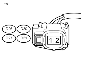
Standard Voltage Tester Connection Condition Specified Condition D26-1 - Body ground Power switch on (IG) 11 to 14 V D30-1 - Body ground Power switch on (IG) 11 to 14 V D27-1 - Body ground Power switch on (IG) 11 to 14 V D31-1 - Body ground Power switch on (IG) 11 to 14 V Table 1. Text in Illustration *a Front view of wire harness connector
(to Fuel Injector Assembly)
- OKClick here
- NGClick here
-
- Click here
INSPECT FUEL INJECTOR ASSEMBLY
-
Check the fuel injector assembly (Click here).
Tip:Perform "Inspection After Repair" after replacing the fuel injector assembly (Click here).
- OKClick here
- NG
REPLACE FUEL INJECTOR ASSEMBLY (Click here)
-
- Click here
CHECK HARNESS AND CONNECTOR (FUEL INJECTOR ASSEMBLY - ECM)
-
Disconnect the fuel injector assembly connectors.
-
Disconnect the ECM connector.
-
Measure the resistance according to the value(s) in the table below.
Standard Resistance Tester Connection Condition Specified Condition D26-2 - D24-20 (#10) Always Below 1 Ω D30-2 - D24-17 (#20) Always Below 1 Ω D27-2 - D24-18 (#30) Always Below 1 Ω D31-2 - D24-19 (#40) Always Below 1 Ω D26-2 or D24-20 (#10) - Body ground Always 10 kΩ or higher D30-2 or D24-17 (#20) - Body ground Always 10 kΩ or higher D27-2 or D24-18 (#30) - Body ground Always 10 kΩ or higher D31-2 or D24-19 (#40) - Body ground Always 10 kΩ or higher
- OK
PROCEED TO NEXT SUSPECTED AREA SHOWN IN PROBLEM SYMPTOMS TABLE (Click here)
- NG
REPAIR OR REPLACE HARNESS OR CONNECTOR
-
- Click here
CHECK HARNESS AND CONNECTOR (FUEL INJECTOR ASSEMBLY - NO. 1 INTEGRATION RELAY)
-
Disconnect the fuel injector assembly connectors.
-
Remove the No. 1 integration relay from the engine room relay block and junction block assembly.
-
Measure the resistance according to the value(s) in the table below.
Standard Resistance Tester Connection Condition Specified Condition D26-1 - 1A-3 Always Below 1 Ω D30-1 - 1A-3 Always Below 1 Ω D27-1 - 1A-3 Always Below 1 Ω D31-1 - 1A-3 Always Below 1 Ω D26-1 or 1A-3 - Body ground Always 10 kΩ or higher D30-1 or 1A-3 - Body ground Always 10 kΩ or higher D27-1 or 1A-3 - Body ground Always 10 kΩ or higher D31-1 or 1A-3 - Body ground Always 10 kΩ or higher
- OK
CHECK ECM POWER SOURCE CIRCUIT (Click here)
- NG
REPAIR OR REPLACE HARNESS OR CONNECTOR
-