FRONT SUSPENSION MEMBER INSTALLATION

Info Added 2017-08-02 ![]()
PROCEDURE
-
INSTALL HOLE PLUG
-
Install 10 hole plugs to the front frame assembly.
Tech Tips
There are 4 different shapes of hole plug.
-
-
INSTALL FRONT SUSPENSION MEMBER BODY MOUNTING REAR CUSHION LH
-
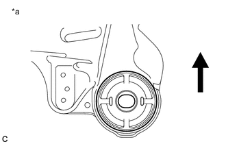
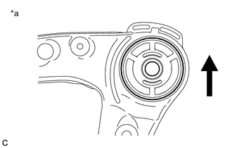
Text in Illustration *a View from Underneath 
Front of the Vehicle Temporarily install a new front suspension member body mounting rear cushion LH while confirming the installation direction.
Note
Position the front suspension member body mounting rear cushion LH in the correct direction.
-
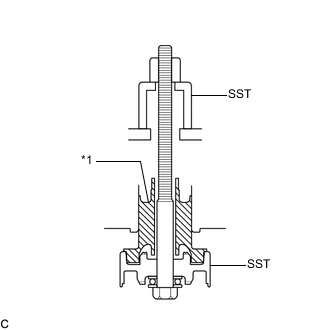
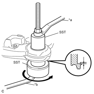
Text in Illustration *1 Front Suspension Member Body Mounting Rear Cushion LH Install SST as shown in the illustration.
- SST
- 09830-10010 ( 09830-01010, 09830-01020, 09830-01030, 09830-01060 )
-
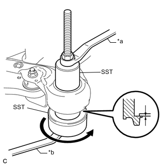
Text in Illustration *a Hold *b Turn Using SST, install the front suspension member body mounting rear cushion LH as shown in the illustration.
Note
Check that there is no clearance between the front frame assembly and the front suspension member body mounting rear cushion LH.
-
-
INSTALL FRONT SUSPENSION MEMBER BODY MOUNTING REAR CUSHION RH
-
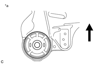
Text in Illustration *a View from Underneath Front of the Vehicle Temporarily install a new front suspension member body mounting rear cushion RH while confirming the installation direction.
Note
Position the front suspension member body mounting rear cushion RH in the correct direction.
-
Install SST using the same procedure as the front suspension member body mounting rear cushion LH.
- SST
- 09830-10010 ( 09830-01010, 09830-01020, 09830-01030, 09830-01060 )
-
Using SST, install the front suspension member body mounting rear cushion RH.
- SST
- 09830-10010 ( 09830-01010, 09830-01020, 09830-01030, 09830-01060 )
Tech Tips
Perform the same procedure as the LH side.
-
-
INSTALL FRONT SUSPENSION MEMBER BODY MOUNTING FRONT CUSHION
-
Text in Illustration *a View from Underneath Front of the Vehicle Temporarily install a new front suspension member body mounting front cushion while confirming the installation direction.
Note
Position the front suspension member body mounting front cushion in the correct direction.
-
Install SST using the same procedure as the front suspension member body mounting rear cushion LH.
- SST
- 09830-10010 ( 09830-01010, 09830-01020, 09830-01030, 09830-01060 )
-
Text in Illustration *a Hold *b Turn Using SST, install the front suspension member body mounting front cushion as shown in the illustration.
- SST
- 09830-10010 ( 09830-01010, 09830-01020, 09830-01030, 09830-01060 )
Note
Check that there is no clearance between the front frame assembly and the front suspension member body mounting front cushion.
-
-
INSTALL FRONT SUSPENSION MEMBER BODY MOUNTING REAR STOPPER
-
Install the 2 front suspension member body mounting rear stoppers to the front frame assembly.
-
-
INSTALL FRONT SUSPENSION MEMBER BODY MOUNTING FRONT STOPPER
-
Install the 2 front suspension member body mounting front stoppers to the front frame assembly.
-
-
INSTALL FRONT SUSPENSION MEMBER DYNAMIC DAMPER
-
Install the front suspension member dynamic damper to the front frame assembly with the 2 bolts.
- Torque:
- 29 N*m { 296 kgf*cm, 21 ft.*lbf }
-
-
INSTALL FRONT LOWER NO. 1 SUSPENSION ARM SUB-ASSEMBLY LH
-
Install the front lower arm bushing stopper to the front lower No. 1 suspension arm sub-assembly.
-
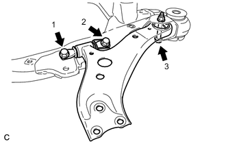
Install the front lower No. 1 suspension arm sub-assembly to the front frame assembly with the 3 bolts and nut in the order shown in the illustration.
- Torque:
- Bolt 1, 2
- 200 N*m { 2039 kgf*cm, 148 ft.*lbf }
- Bolt 3
- 135 N*m { 1377 kgf*cm, 100 ft.*lbf }
Note
While keeping the nut from rotating, tighten the bolt.
-
-
INSTALL FRONT LOWER NO. 1 SUSPENSION ARM SUB-ASSEMBLY RH
Tech Tips
Perform the same procedure as the LH side.
-
INSTALL STEERING LINK ASSEMBLY
-
INSTALL FRONT STABILIZER BAR WITH FRONT STABILIZER LINK ASSEMBLY
-
Install the front stabilizer bar with 2 front stabilizer link assemblies to the front frame assembly.
-
-
INSTALL FRONT NO. 1 STABILIZER BRACKET LH
-
INSTALL FRONT NO. 1 STABILIZER BRACKET RH
Tech Tips
Perform the same procedure as the LH side.
-
INSTALL ENGINE MOUNTING INSULATOR LH
-
INSTALL ENGINE MOUNTING INSULATOR RH
-
INSTALL FRONT ENGINE MOUNTING INSULATOR
-
INSTALL FRONT FRAME ASSEMBLY