CAUTION / NOTICE / HINT
-
Use the same procedure for the RH side and LH side.
-
The procedure listed below is for the LH side.
PROCEDURE
- Click here
INSTALL REAR AXLE CARRIER SUB-ASSEMBLY
-
Install the rear axle carrier sub-assembly to the rear shock absorber assembly with the 2 bolts and 2 nuts.
290 N*m 2957 kgf*cm 214 ft.*lbf Note:While keeping the bolts from rotating, tighten the nuts.
Tip:Insert the bolt from the rear of the vehicle.
-
- Click here
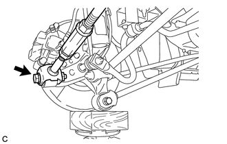
TEMPORARILY TIGHTEN REAR NO. 1 SUSPENSION ARM ASSEMBLY
-
Connect the rear No. 1 suspension arm assembly (outer side) to the rear axle carrier sub-assembly with the bolt and nut.
Note:When temporarily tightening the bolt, keep the nut from rotating.
Tip:Insert the bolt from the front of the vehicle.
-
- Click here
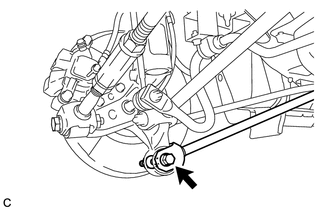
TEMPORARILY TIGHTEN REAR NO. 2 SUSPENSION ARM ASSEMBLY
-
Connect the rear No. 2 suspension arm assembly (outer side) to the rear axle carrier sub-assembly with the bolt and nut.
Note:When temporarily tightening the bolt, keep the nut from rotating.
Tip:Insert the bolt from the rear of the vehicle.
-
- Click here
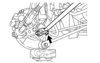
TEMPORARILY TIGHTEN REAR STRUT ROD ASSEMBLY
-
Temporarily tighten the rear strut rod assembly (rear side) to the rear axle carrier sub-assembly with the bolt and nut.
Note:Since a stopper nut is used, turn the bolt.
Tip:Insert the bolt from the inside of the vehicle.
-
- Click here
INSTALL REAR AXLE HUB AND BEARING ASSEMBLY
- Click here
CONNECT SKID CONTROL SENSOR WIRE
- Click here
INSTALL REAR DISC
- Click here
INSTALL PARKING BRAKE SHOE ADJUSTING HOLE PLUG
- Click here
INSTALL REAR DISC BRAKE CALIPER ASSEMBLY
- Click here
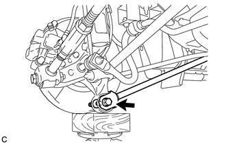
STABILIZE SUSPENSION
-
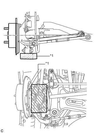
Jack up the rear axle carrier sub-assembly, placing a wooden block under it to avoid damage. Apply load to the suspension so that the installed bolt of the rear No. 1 suspension arm assembly (inner side) is horizontally aligned with the center of the rear axle hub.
Table 1. Text in Illustration *1 Wooden Block CAUTION:Do not jack up the rear axle carrier sub-assembly too high as the vehicle may fall.
Note:
-
When jacking up the rear axle carrier sub-assembly, be sure to jack it up slowly.
-
Make sure to perform this operation with the vehicle kept as low as possible.
-
-
- Click here
FULLY TIGHTEN REAR NO. 1 SUSPENSION ARM ASSEMBLY
-
Fully tighten the bolt.
100 N*m 1020 kgf*cm 74 ft.*lbf Note:Since a stopper nut is used, fully tighten the bolt.
-
- Click here
FULLY TIGHTEN REAR NO. 2 SUSPENSION ARM ASSEMBLY
-
Fully tighten the bolt.
100 N*m 1020 kgf*cm 74 ft.*lbf Note:Since a stopper nut is used, fully tighten the bolt.
-
- Click here
FULLY TIGHTEN REAR STRUT ROD ASSEMBLY
-
Fully tighten the bolt.
80 N*m 816 kgf*cm 59 ft.*lbf Note:Since a stopper nut is used, fully tighten the bolt.
-
- Click here
INSTALL REAR HEIGHT CONTROL SENSOR SUB-ASSEMBLY (for RH Side)
- Click here
CONNECT CABLE TO NEGATIVE AUXILIARY BATTERY TERMINAL
-
Connect the cable to the negative (-) auxiliary battery terminal (Click here).
-
Connect the reservoir level switch connector.
-
Clear the DTCs (Click here).
-
- Click here
ADJUST PARKING BRAKE
- Click here
INSTALL REAR WHEEL
103 N*m 1049 kgf*cm 76 ft.*lbf - Click here
INSPECT AND ADJUST REAR WHEEL ALIGNMENT
- Click here
CHECK FOR SPEED SENSOR SIGNAL